
Tools
Parts
-
-
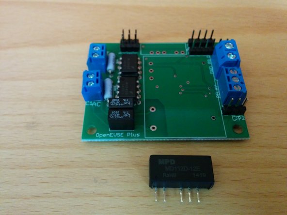
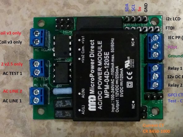
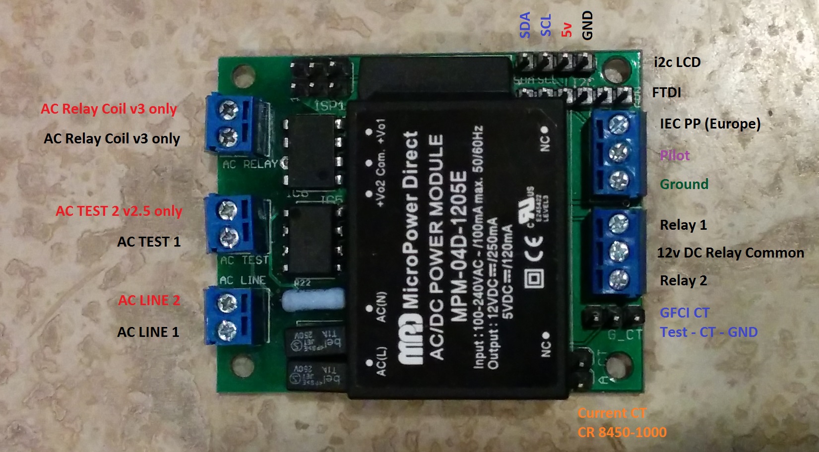
Break header pins to match the holes and solder into place.
-
Take care not to touch other components in the area with your soldering iron.
-
Optional - If you are measuring current with the CR Magnetics 8450-1000, you will need an additional 2-pin header for the "A_CT" connection.
-
-
-
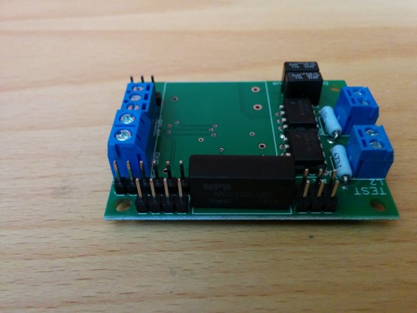
Solder the DC to DC converter to the OpenEVSE board.
-
Take care not to touch other components with your soldering iron.
-
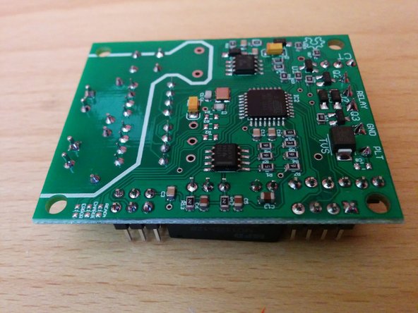
Trim the excess leads off the DC to DC converter.
-
-
-
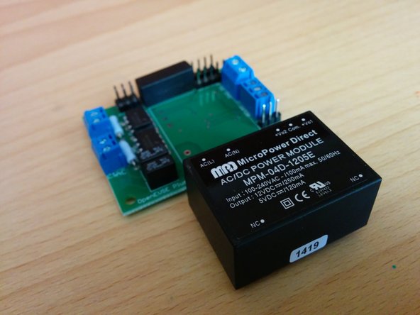
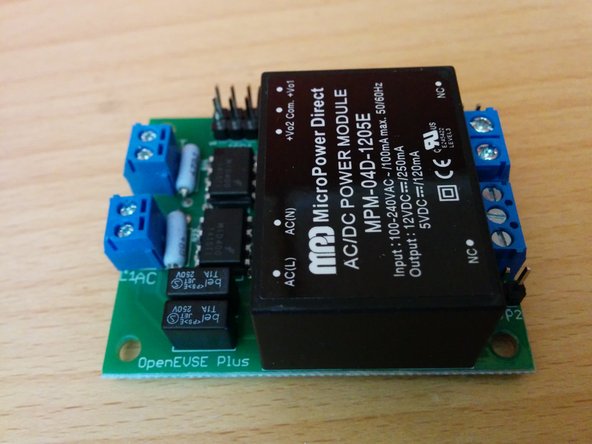
Solder the AC to DC converter to the OpenEVSE board.
-
Take care not to touch other components while you solder the power supply leads.
-
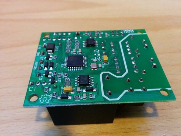
Trim any excessively long leads from the bottom of the board.
-


Cancel: I did not complete this guide.
21 other people completed this guide.