Difficulty
Moderate
Steps
11
Time Required
00:30:00 - 02:00:00

Featured Guide
This guide has been found to be exceptionally cool by the site's staff.

User-Contributed Guide
This guide is not managed by the site's staff.
Introduction
OpenEVSE Store - Purchase this OpenEVSE Kit
Warning Assembly of a Electric Vehicle charging station requires wiring Alternating Current (AC) components that will be exposed to voltages from 100 to 250v. If you do not have the experience and knowledge required to safely work with AC voltages please consult with an experienced electrician for assistance and inspection of your work.
Note Regularly inspect your charging station. Pay special attention to excess heat, components, handles, and wiring will be warm but they should not be HOT...
Always Disconnect your charging station from power before performing an inspection and/or maintenance
-
-
These documents will assist with the steps that follow.
-
OpenEVSE Board Pins and Connections Download PDF
-
Schematic Diagram Download PDF
-
-
-
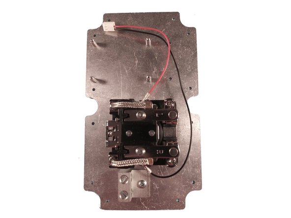
Position the plate with the FOUR holes for the OpenEVSE controller up top-left.
-
Mount the FOUR 4.5 Hex x 10mm standoffs to the top side of the plate with FOUR M2.5 x 6 mm screws.
-
Tip - use blue LOCTITE on each screw to ensure it remains tight.
-
Mount the Struthers-Dunn relay using TWO 1/2" self threading screws.
-
Mount ground bar to the plate with ONE 1/4" self threading screws.
-
-
-
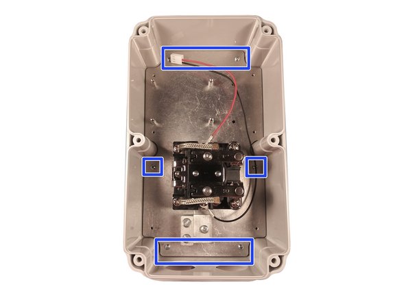
Attach the relay coil harness.
-
Mount plate in enclosure with SIX coarse threaded 6mm screws.
-
Install the TWO cable glands.
-
-
-
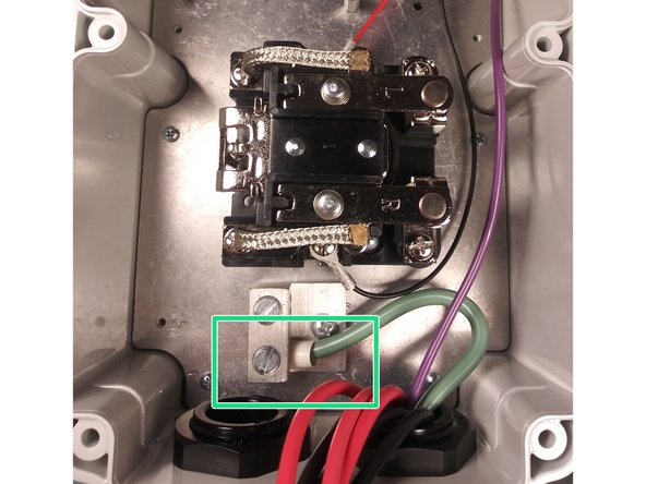
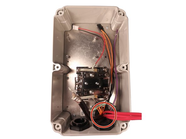
Insert EV Cable through the Cable Gland on the right and tighten.
-
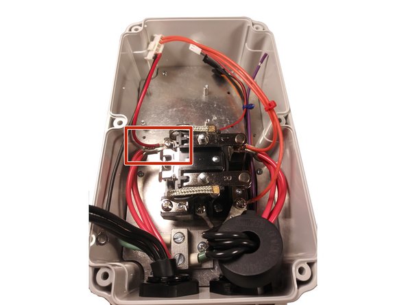
Connect the ground wire to the ground block.
-
Route the ground, pilot and coil wires low in the enclosure to avoid crossing any high voltage wires or components.
-
Thread ALL hot and neutral lines through the 4 wire GFCI coil with the orange self test loop.
-
Do not thread the ground wire or pilot wire through.
-
Advanced Series Only - Thread EITHER hot OR neutral through the Current Measurement Coil.
-
Tip - zip tie smaller wires together near the top and bottom to keep them neat and out of the way.
-
-
-
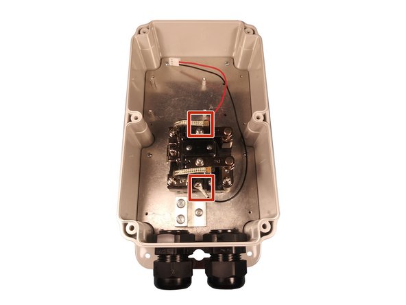
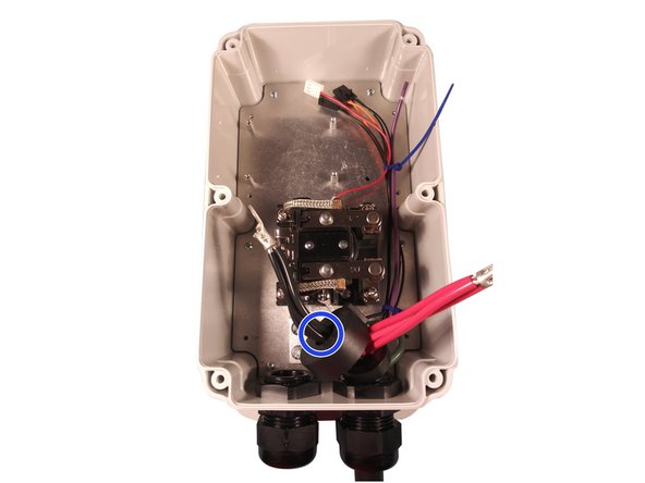
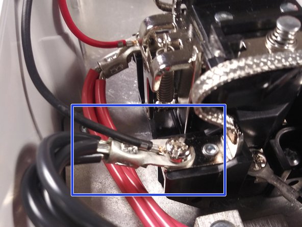
Screw the ring terminals on the EV cable power conductors to the relay along with the wiring harness.
-
Connect the longer lead on the harness to the bottom position and the shorter the top position.
-
Tip - run the top power wire in the middle of the enclosure with the smaller low voltage wires on the bottom. Ensure they is plenty of clearance.
-
Tip - run the bottom power wire high in the enclosure and angled away from the top power wire. Ensure there is plenty of clearance.
-
-
-
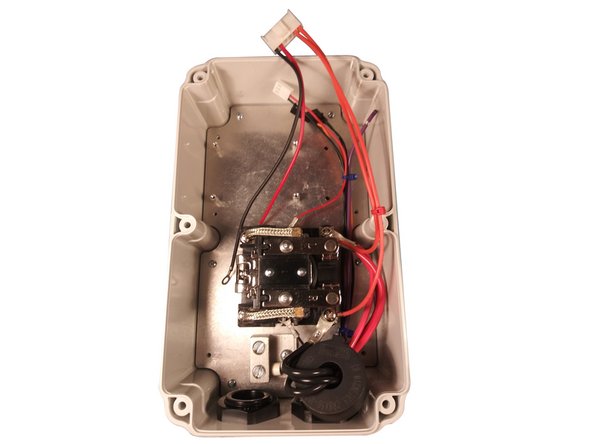
Insert the input cable through the left gland.
-
Connect the ground wire to the ground block.
-
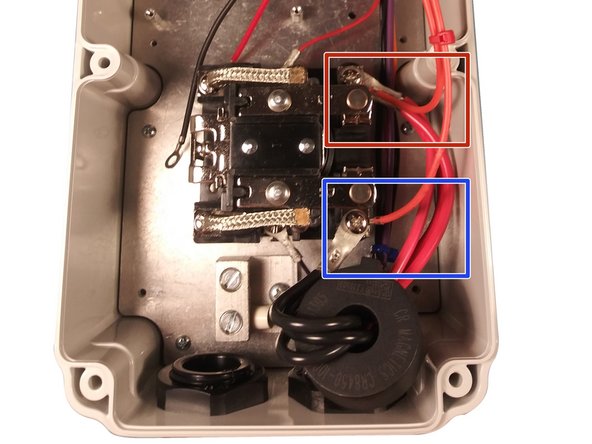
Screw the ring terminal on the EV cable power conductor to the top position of relay along with the red wire on the wiring harness.
-
Screw the ring terminal on the EV cable power conductor to the bottom position of relay along with the black wire on the wiring harness.
-
Tip - run the top power wire in low in the enclosure.
-
Tip - run the bottom power wire high in the enclosure and angled away from the top power wire. Ensure there is plenty of clearance.
-
-
-
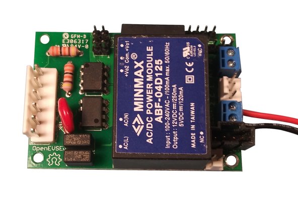
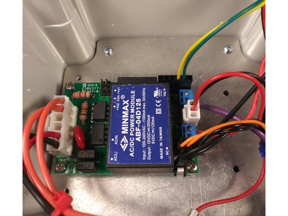
Static sensitive - Lift controller by board edges or AC/DC power supply. Do not touch components.
-
Advanced Series Only
-
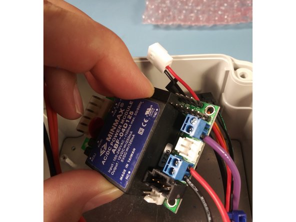
Connect the red wire on the WiFi harness to +12v DC screw terminal on the OpenEVSE controller.
-
Connect the black wire on the WiFi harness to ground screw terminal on the OpenEVSE controller.
-
Connect the pilot wire to the OpenEVSE controller.
-
Mount OpenEVSE controller to the hex standoffs with FOUR M2.5 x 6mm screws.
-
-
-
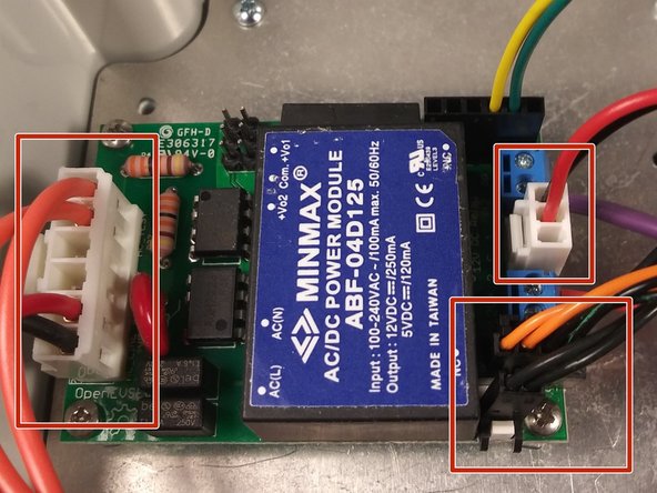
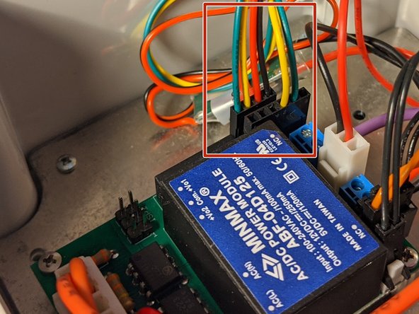
View OpenEVSE v5 Diagram in previous step for wires named below.
-
Connect the keyed wiring harnesses to OpenEVSE controller.
-
Wire colors may vary.
-
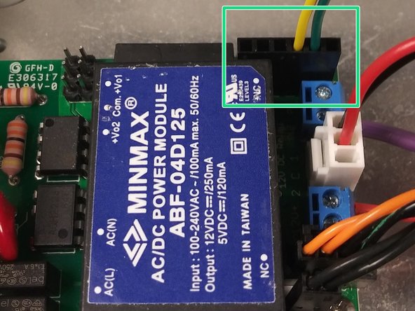
Connect the WiFI data cable to the controller with the green wire closest to the board edge.
-
-
-
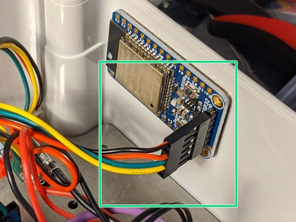
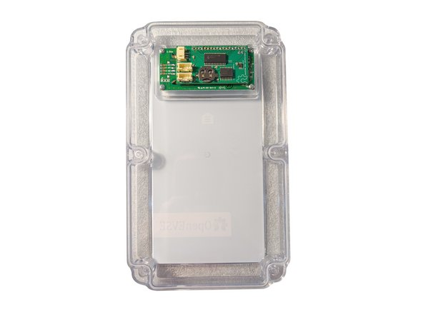
Static sensitive - Lift WiFi by board edges. Do not touch components.
-
Peel the red backing on the 3M VHB industrial mounting tape.
-
Install the WiFi module with the antenna in the top of the enclosure and the connector facing down.
-
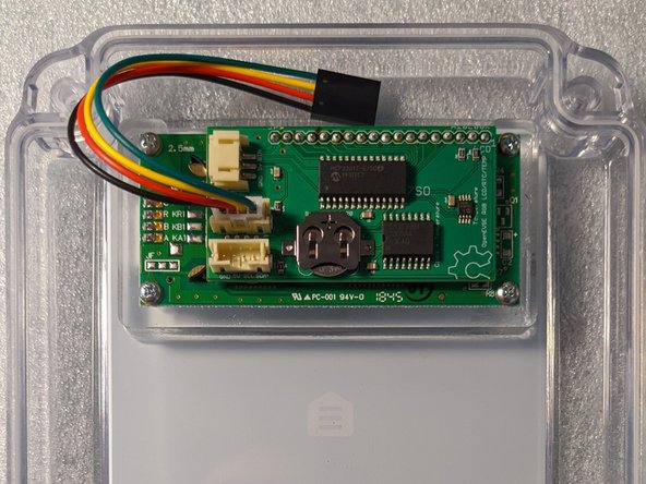
Connect the WiFi harness.
-
Connect the LCD harness.
-
-
-
Static sensitive - Lift display by board edges. Do not touch components.
-
Attach display with FOUR coarse threaded 6 mm screws.
-
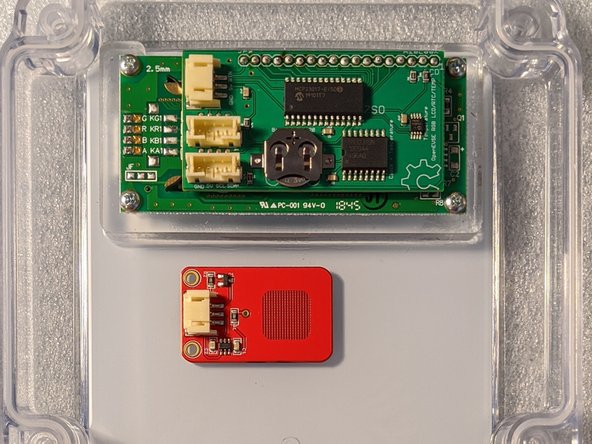
Standard - No button. All options and settings are configurable via WiFi
-
Option add on - Not Included - Touch button - Remove film from the double sided tape and mount touch button.
-
Line up square grid area with the menu icon printed on the enclosure.
-
Option - Not Included - A CR12xx (CR1216 - CR1220 - CR1225) battery may be installed to keep time on clock during periods with no WiFi and no grid no power.
-
-
-
Connect display harness to the lower port on the display module
-
Place the enclosure lid on and ensure there are no wires pinched in the lid.
-
Start all SIX 6-32 x 1 1/4" screws before tightening.
-
Tighten all SIX so the lid slightly squishes down slightly on the clear seal embedded into the lid. Do not over-tighten.
-
Mount station with template. Mounting Your Charging Station Quick Start Guide
-
Setup Wifi - WiFi - Join Network Quick Start Guide
-