Reputation over time
It looks like this user hasn't gained any reputation yet.
Once they have, you'll be able to view a graph of their reputation gained over time.
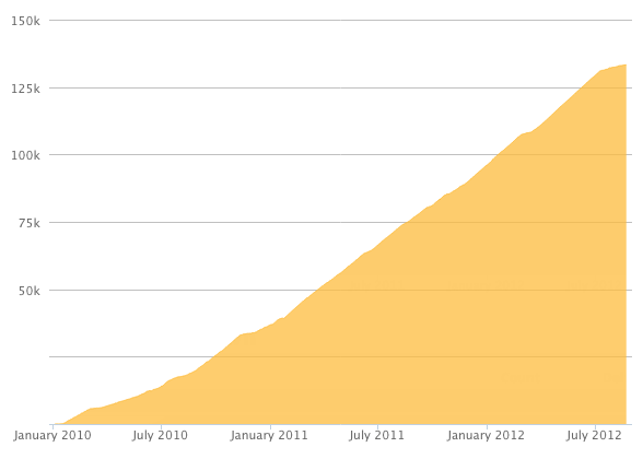
Here's a preview of what the graph will look like:
Reputation Breakdown
No reputation gained yet.
378
If you also got the ribbon cable, it’s very difficult to figure out which way to connect it. I double checked it twice with the pictures/yellow wire location/red ribbon mark/”1” on the OpenEVSE and still got it wrong. But worked when I flipped it. Could use some pictures for the ribbon cable and also for the older OpenEVSE with the 6 pin connector rotated 90 degrees from these pictures.
The programmer I received a few weeks ago now has a ribbon connector instead of all the wires. I followed the pictures carefully and it seemed like the red line on the ribbon was opposite to where the yellow wire was on the programmer. I therefore lined the other side up with the 1 on the OpenEVSE. It didn’t work. I turned it around and it did work so I’m not sure where the parity mismatch happened, but I guess if it doesn’t work, reverse it and try it the other way? This could use updated instructions for the ribbon cable. My 2018 OpenEVSE also had the 6 pin connector rotated 90 degrees from shown in the pictures.
Services - EmonCMS
Apparently the sealing washers are not required with the 1/4” thick LCD window and are not included after Feb 2018.
Where are the instructions for the WiFi wiring? Step 2 shows a location for the board, and Step 5 shows connection of the UBEC power supply which I assumes powers the board. How do you connect the power cable to the WiFi board and how do you connect a ?data? cable to the OpenEVSE board?
Tools: Needs a small flat head screw driver ~3mm for 8 connections on the OpenEVSE board. Also a Red Robertson (square head) or larger flat head screw driver for tightening the green set screws in the ground bar header.
1. ++ on the value of perfectly vertical pics of the board so the wire locations are clear & not affected by parallax.
2. A lot neater if you cut the three red spade lug wires about 2” shorter since they all go to the near side of the contactor.
3. Ground wire was black and unstripped in my kit. (Green dot instruction)
4. Don’t attach the ring spade lugs to the contactor yet, just plug them into the wires, screw them down after connecting the J1772 (step 9) and the power cord (step 10). Otherwise you will just take the screws out after you have just put them in with the ring connectors.
Yes. The instruction has a black dot. 1st pic seems to show it connected to the 3rd green set screw from the top.