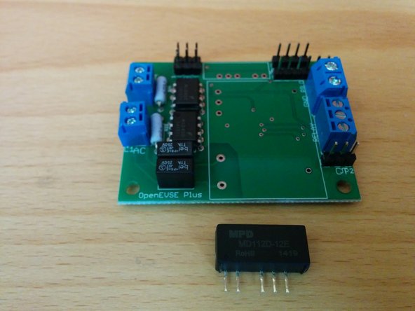
1. Carefully remove components from antistatic bag. Carefully remove components from antistatic bag.
    • Carefully remove components from antistatic bag.

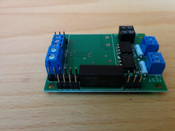
  2. Break header pins to match the holes and solder into place. Take care not to touch other components in the area with your soldering iron. Optional - If you are measuring current with the CR Magnetics 8450-1000, you will need an additional 2-pin header for the "A_CT" connection.
    • Break header pins to match the holes and solder into place.

    • Take care not to touch other components in the area with your soldering iron.

    • Optional - If you are measuring current with the CR Magnetics 8450-1000, you will need an additional 2-pin header for the "A_CT" connection.

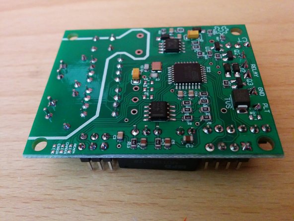
  3. Solder the DC to DC converter to the OpenEVSE board. Take care not to touch other components with your soldering iron. Trim the excess leads off the DC to DC converter.
    • Solder the DC to DC converter to the OpenEVSE board.

    • Take care not to touch other components with your soldering iron.

    • Trim the excess leads off the DC to DC converter.

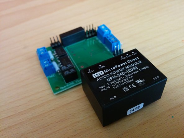
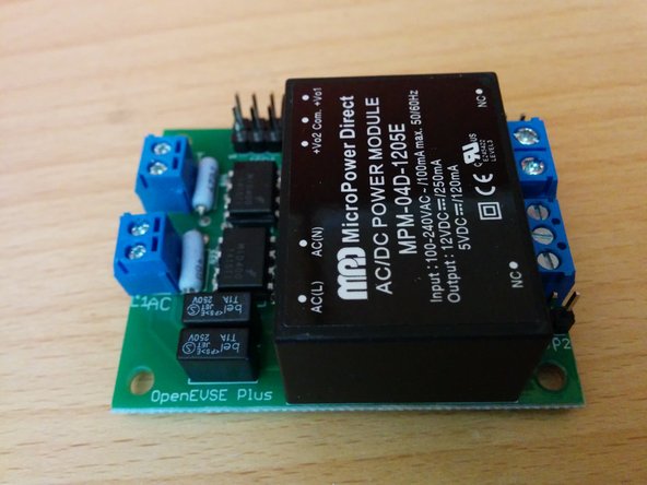
  4. Solder the AC to DC converter to the OpenEVSE board. Take care not to touch other components while you solder the power supply leads. Trim any excessively long leads from the bottom of the board.
    • Solder the AC to DC converter to the OpenEVSE board.

    • Take care not to touch other components while you solder the power supply leads.

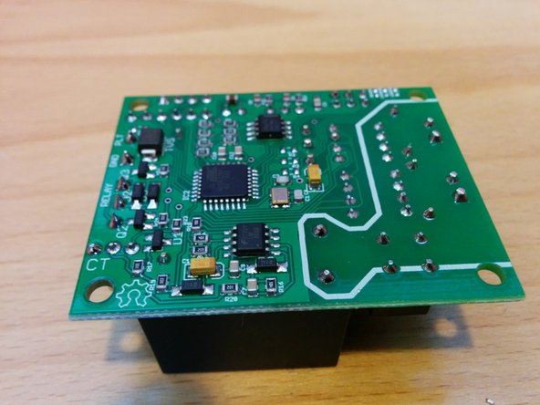
    • Trim any excessively long leads from the bottom of the board.

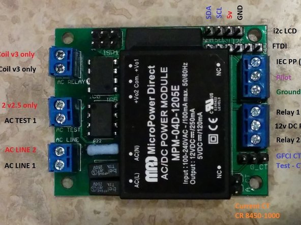
  5. Connection Diagram Plus v2.5 and v3 - JPG
    • Connection Diagram Plus v2.5 and v3 - JPG

Finish Line

21 other people completed this guide.

Christopher Howell

Member since: 07/05/2014

7,127 Reputation

21 Guides authored

0 Comments

Add Comment

View Statistics:

Past 24 Hours: 0

Past 7 Days: 0

Past 30 Days: 6

All Time: 12,657