
Difficulty
Moderate
Steps
12
Time Required
00:30:00

In Progress
This guide is currently being written. Reload periodically to see the latest changes.
-
-
This guide provides the assembly procedure for IEC Type 2 "Mennekes" cable from parts available from at OpenEVSE.
-
-
-
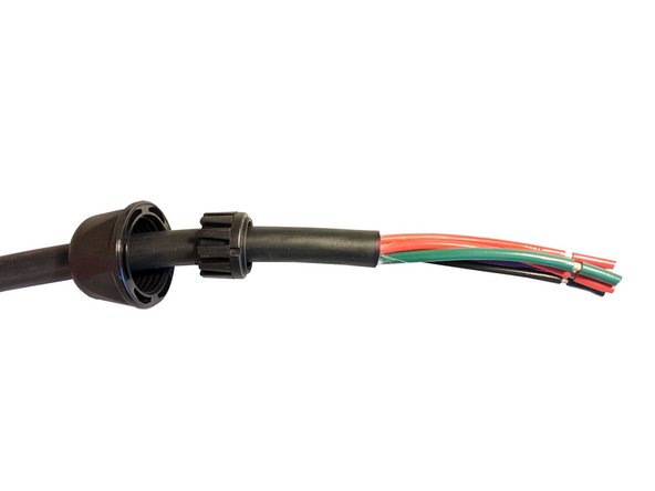
This guide uses 40A EVJT cable available from OpenEVSE.
-
Remove 3.25 inches of the outer jacket.
-
Strip and retain insulation from RED, BLACK and GREEN wire 1/2 inch (0.50").
-
Strip and retain insulation from Purple wire 3/8 inch (0.375")
-
Strip and retain insulation from Purple wire 3/8 inch (0.375")
-
-
-
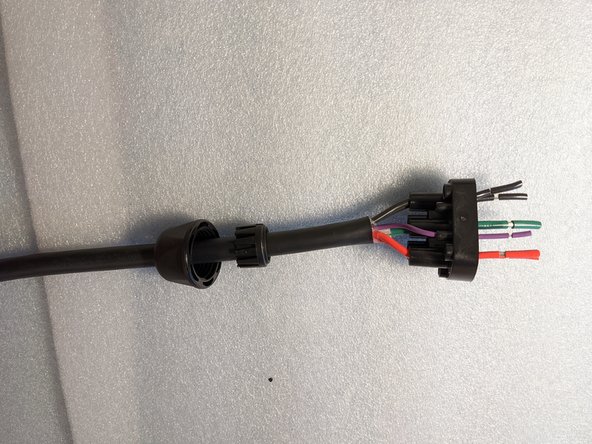
Slide gland onto the cable. The notched end should face toward the stripped conductors.
-
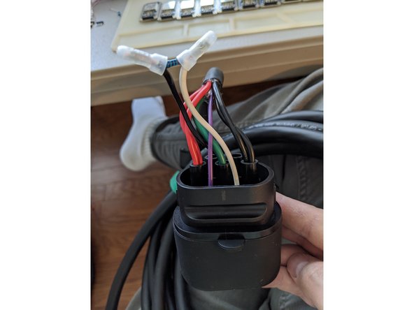
Insert conductors into the guide/seal, abbreviations are molded into the plastic part. PE = GREEN, CP = PURPLE, N - RED, L - BLACK
-
-
-
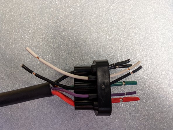
Cut 6" each of BLACK and WHITE 18AWG stranded wire.
-
Strip and retain 0.50" of insulation off both ends of the BLACK and WHITE wires.
-
Insert the 18AWG BLACK wire in the PE position in addition to the GREEN wire.
-
Insert a 18AWG WHITE wire in the hole labeled PP.
-
-
-
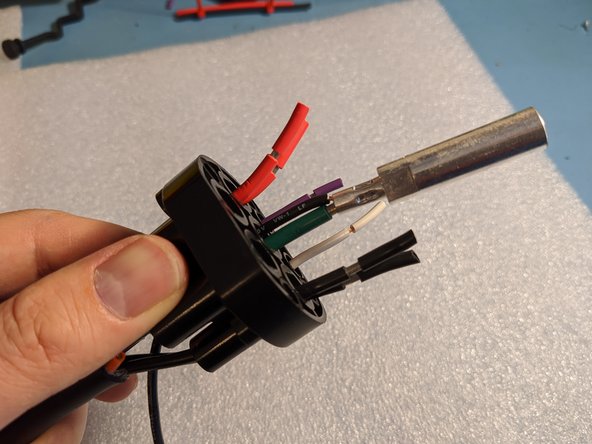
Remove insulation from the GREEN and BLACK wire.
-
Insert the ground pin on the 10AWG GREEN wire and the 18AWG BLACK Proximity wire.
-
Crimp Ground pin with Pico Corporation 400B pneumatic crimping tool at 80PSI.
-
Required Die Pico 414DA-8N
-
Require locator - OpenEVSE IEC Power/Ground
-
-
-
Remove the insulation on all the RED and BLACK power wires.
-
Insert the power pin on the BLACK wire(s) and crimp.
-
Insert the power pin in the RED wire(s) and crimp.
-
Crimp Power pins with Pico Corporation 400B pneumatic crimping tool at 80PSI.
-
Required Die Pico 414DA-8N
-
Require locator - OpenEVSE IEC Power/Ground
-
-
-
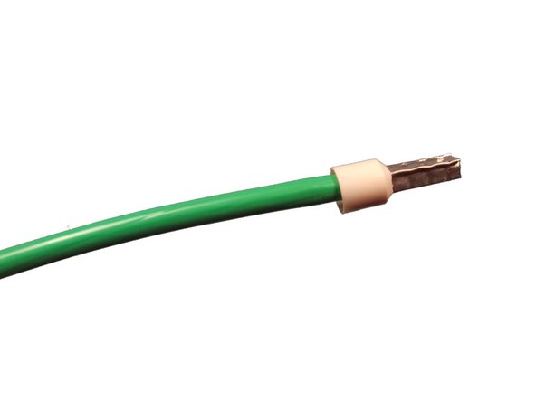
Insert the signal pin on the PURPLE wire and crimp.
-
Insert the signal pin on the WHITE wire and crimp.
-
Crimp Ground pin with Pico Corporation 400B pneumatic crimping tool at 80PSI.
-
Required Die Pico 414DA-16N
-
Require locator - OpenEVSE J1772 Signal
-
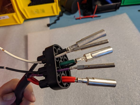
Slide up the pin guide onto the pins.
-
Add power pins to the empty to positions marked L2 and L3
-
Slide O ring on each power pin.
-
-
-
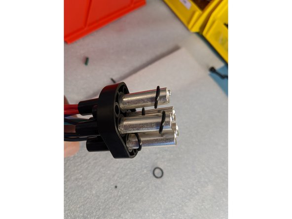
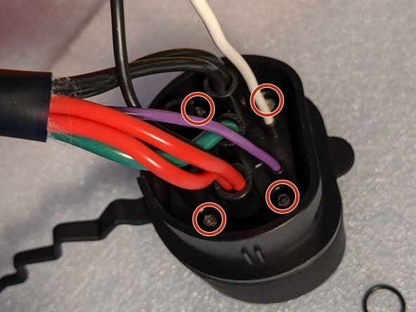
Insert pins into the connector housing.
-
Screw pin guide to the connector housing using 4 - 12 mm screws.
-
-
-
Remove the insulation off all BLACK and WHITE wires.
-
Twist lead from resistor on both black and white wire from bottom to top and crimp.
-
-
-
Secure cable in the strain relief leaving at least 1/4" exposed.
-
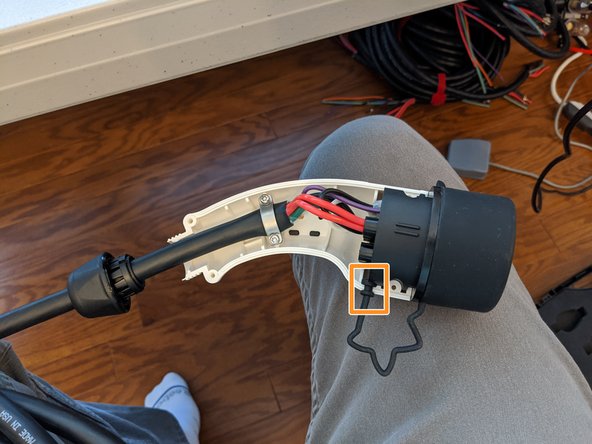
Insert nose in bottom shell.
-
Position dust cover end in notch.
-
-
-
Insert dust cap end in shell halves.
-
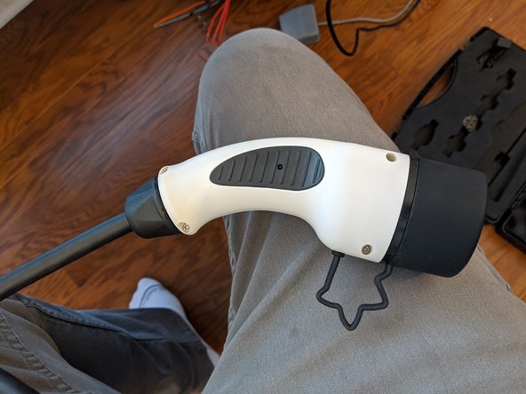
Insert and tighten 16 mm screws in holes marked in RED.
-
Insert and tighten 12 mm screws in positions marked in BLUE.
-
Tighten Cable Gland
-
-
-
Remove insulation and crimp ring terminal on BLACK wires.
-
Remove insulation and crimp ring terminals on RED wires.
-
Remove insulation and Crimp Sleeve ferrule on GREEN wire.
-


One Comment
Just wanted to note that this wiring is Correct for USA, Black is Hot. please Pay Careful attention to the wording in step 3, Red = N and Black = L. This is not the case in other regions around the globe. make sure you are using the wiring colours specific to your region. for instance in my region Black = N and Red = L.