-
-
Unplug your station or turn off circuit breaker. Never work on your station energized.
-
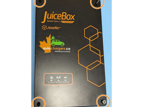
Remove the 4 Torx T10 Screws.
-
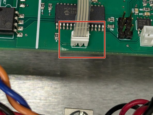
Carefully lift the lid and disconnect the ribbon cable for the indicator lights.
-
-
-
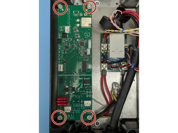
Remove the 4 11/32" nuts on each corner of the controller board.
-
Remove all of the connectors. Note most have tabs which when pressed release the connector.
-
Remove the circuit board.
-
-
-
Install the OpenEVSE controller board.
-
Secure the controller with the 4 11/32" nuts.
-
-
-
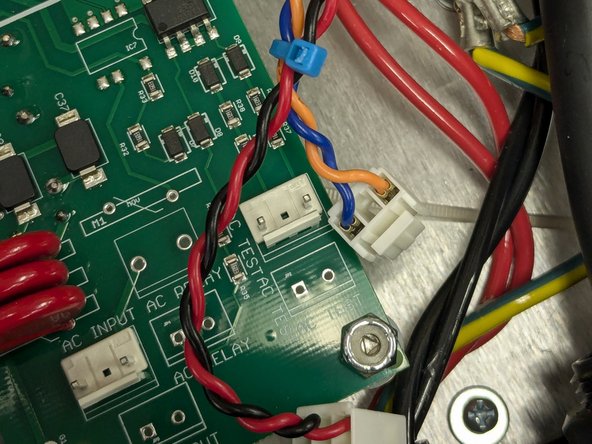
Identify the AC wires coming from the circuit board/Relay Module. Tie wrap them together.
-
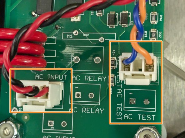
Connect AC_INPUT (RED and BLACK) and AC_TEST (BLUE and ORANGE)
-
-
-
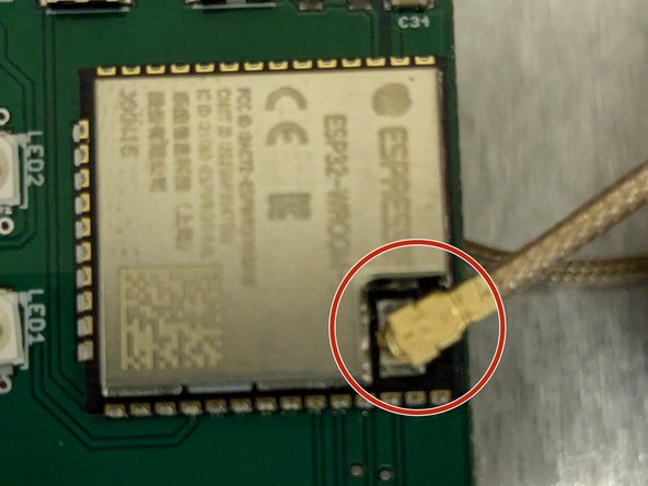
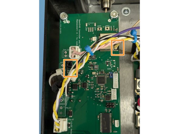
Connect Antenna wire to the WiFi module
-
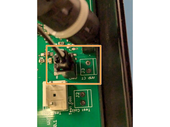
Connect the donut coil WITHOUT the additional wire wrap to the AMP_CT connector. One Power wire runs through this coil.
-
-
-
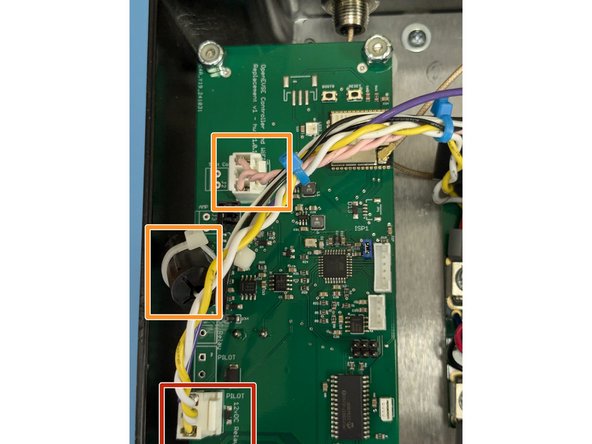
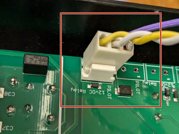
Connect the 3 pin connector that goes to the relay and has the pilot line to the EV handle to the PILOT - 12vDC relay connector.
-
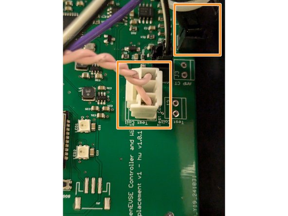
Connect the donut coil WITH the additional wire wrap to the GFCI connector. Connect the wrap to the Test Coil Connector.
-
-
-
Connect the ribbon cable for the indicator lights.
-
Secure the 4 TORX T10 screws on each corner of the lid.
-
6 Comments
I want to add that I was getting the GFCI error when trying to charge. I read another thread and there was a mention that the original OpenEVSE has the wire around the CT five times, instead of one as my Juicebox v1 had. I changed the wire and did the loop 5 times and now it is working fine without the GFCI error. Just a tip for anybody having the problem.
In the my JuiceBox, the original controller has 2032 battery on back side.
Is this controller has such battery? Or saves all info in the flash memory?
Oleg Khovayko - Resolved on Release Reply
Is it possible to connect the color LCD to this? Do you have a guide? Will probably need to cut the lid, but it's okay.
Yiding Zhou - Resolved on Release Reply


