
Difficulty
Easy
Steps
7
Time Required
00:15:00

Featured Guide
This guide has been found to be exceptionally cool by the site's staff.
Quiz
0
Featured Document
-
-
Unplug your station or turn off circuit breaker. Never work on your station energized.
-
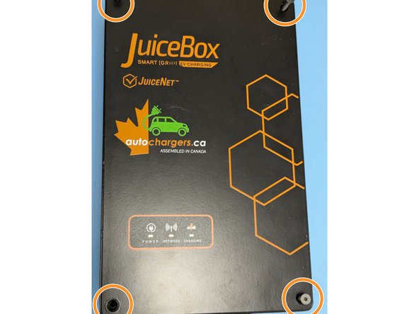
Remove the 4 Torx T10 Screws.
-
Carefully lift the lid and disconnect the ribbon cable for the indicator lights.
-
-
-
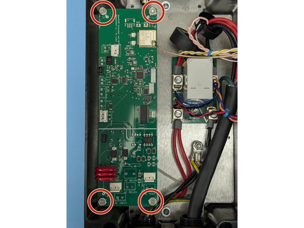
Remove the 4 11/32" nuts on each corner of the controller board.
-
Remove all of the connectors. Note most have tabs which when pressed release the connector.
-
Remove the circuit board.
It was awkward trying to disconnect the cables while the board was loose. I ended up putting the 3/8’ nuts back on while I did that.
Tom Harrington - Resolved on Release Reply
-
-
-
Install the OpenEVSE controller board.
-
Secure the controller with the 4 11/32" nuts.
The washers are on the top right and bottom left mounting screws. These pads have exposed silver pads around the holes.
Bill Hunter - Open Reply
-
-
-
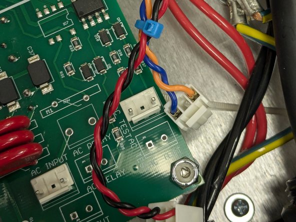
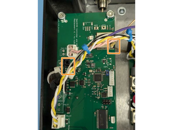
Identify the AC wires coming from the circuit board/Relay Module. Tie wrap them together.
-
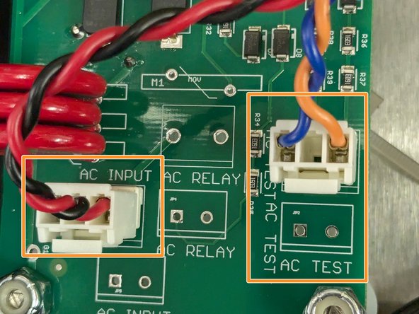
Connect AC_INPUT (RED and BLACK) and AC_TEST (BLUE and ORANGE)
The blue/orange pair was shorter than these photos suggest. I had to reroute it to get it to reach far enough to connect.
Tom Harrington - Resolved on Release Reply
-
-
-
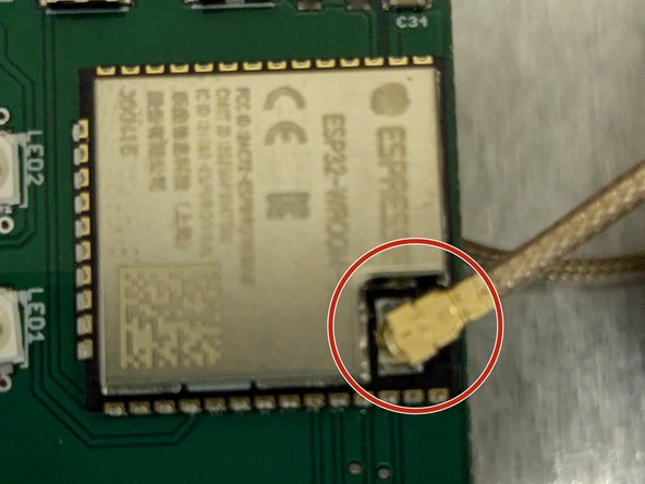
Connect Antenna wire to the WiFi module
-
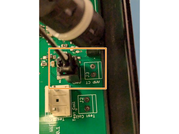
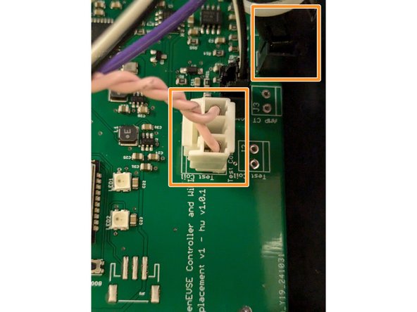
Connect the donut coil WITHOUT the additional wire wrap to the AMP_CT connector. One Power wire runs through this coil.
Hot glue the coax antenna wire down to the board to hold the wire parallel to the board. Without this, the stiff wire could cause the connector to pop out, or cause damage to the connector.
Bill Hunter - Open Reply
-
-
-
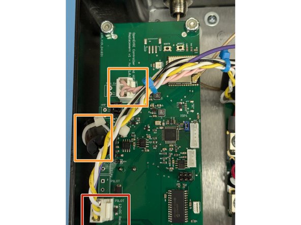
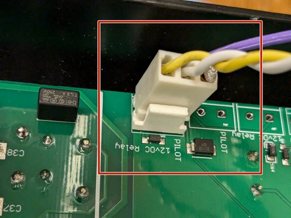
Connect the 3 pin connector that goes to the relay and has the pilot line to the EV handle to the PILOT - 12vDC relay connector.
-
Connect the donut coil WITH the additional wire wrap to the GFCI connector. Connect the wrap to the Test Coil Connector.
The pink wires for the Test Coil Connector aren't quite long enough to reach the socket.
I slid the CT donut coil farther up the wires, and untwisted a little, to make sure there was no strain.
Clarence Dold - Open Reply
-
-
-
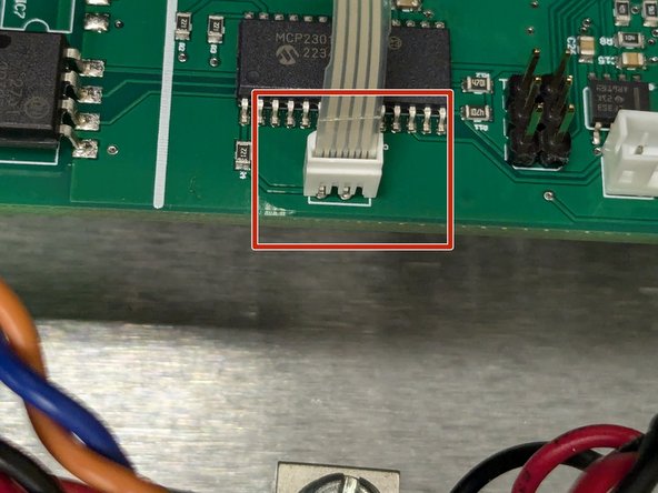
Connect the ribbon cable for the indicator lights.
-
Secure the 4 TORX T10 screws on each corner of the lid.
Luke: > "Try flipping the cable around"
The ribbon cable would like to fit into the connector the wrong way.
Thanks for the clue about looking for the exposed connectors.
Clarence Dold - Open Reply
I cannot attach the ribbon cable for the display lights to the connector. On the old circuit board the connector had a hinged flap that would swing up to release/insert the cable. But I don't see that on the new connector.
Lisa Lampo - Open Reply
I’m having the same experience with the leds. Has anyone solved this?
I was encountering the same thing and I saw your comments. Try flipping the cable around. I looked at it and saw that only 1 side of the cable had conductors exposed. That side needs to face the side of the connector that have metal connectors. The "natural" way (which is without twisting the cable 180 degrees) has the plastic side touching the metal connectors... basically not connected... :-)
Do note that if you have the 3-phase version of this box, the wiring may need to be routed a bit differently. Also the relay is not 12 VDC, instead it’s a 230 VAC refrigeration-style contactor. So you’ll need to deal with that somehow as well (I just found out and am working on it…)
-


Cancel: I did not complete this guide.
One other person completed this guide.
Attached Documents
6 Comments
I want to add that I was getting the GFCI error when trying to charge. I read another thread and there was a mention that the original OpenEVSE has the wire around the CT five times, instead of one as my Juicebox v1 had. I changed the wire and did the loop 5 times and now it is working fine without the GFCI error. Just a tip for anybody having the problem.
In the my JuiceBox, the original controller has 2032 battery on back side.
Is this controller has such battery? Or saves all info in the flash memory?
Oleg Khovayko - Resolved on Release Reply
Is it possible to connect the color LCD to this? Do you have a guide? Will probably need to cut the lid, but it's okay.
Yiding Zhou - Resolved on Release Reply
That unused 6 pin connector on the board looks like it may be connected to the same pins on the microcontroller as they are on the normal v6.5 control board. On the other hand, this board has a WiFi controller built into it. One would need to look at the schematics of the rescue board and the v6.5.1 board to figure out how both of those are wired up, and whether it's still possible.
Simon -
Ours are security T-20, not plain T-10
Ben F - Resolved on Release Reply