
Featured Document
-
-
Unplug your station or turn off the circuit breaker. Never work on your station energized.
-
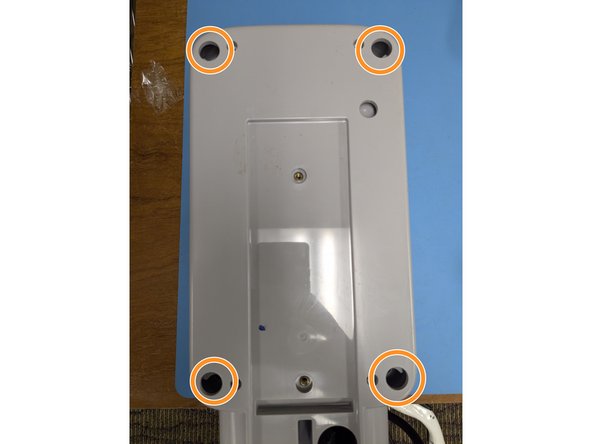
Remove the 4 Phillips head screws.
-
Carefully lift the lid and disconnect the cable for the indicator lights.
-
-
-
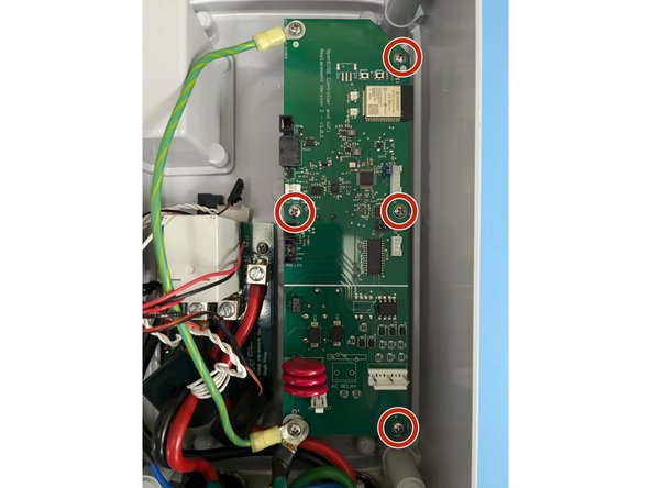
Remove the 6 Phillips head screws on the controller board.
-
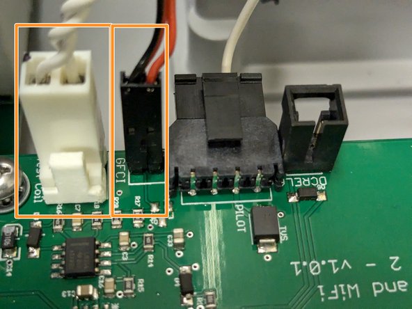
Remove all the connectors. Note most have tabs which when pressed release the connector.
-
Remove the circuit board.
-
-
-
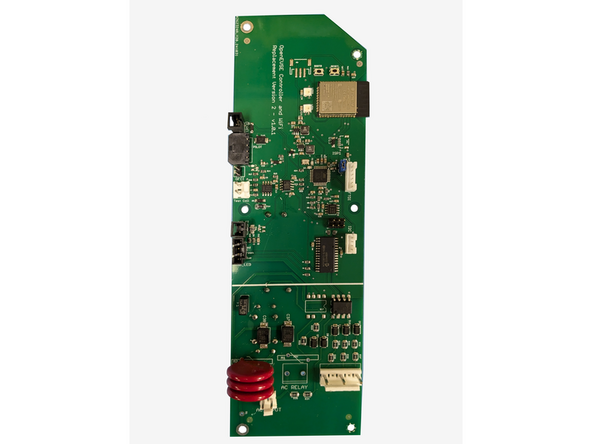
Install the OpenEVSE controller.
-
Secure with the 6 Phillips screws removed in the previous step.
-
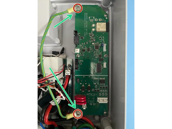
Add the single green wire under the top left position.
-
Add all 3 green wires under the bottom left position with the longest screw.
-
-
-
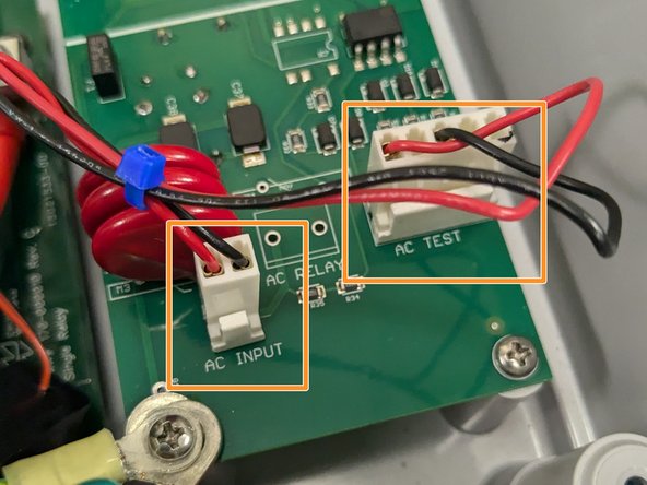
Identify the AC wires coming from the circuit board/relay module. Tie wrap them together.
-
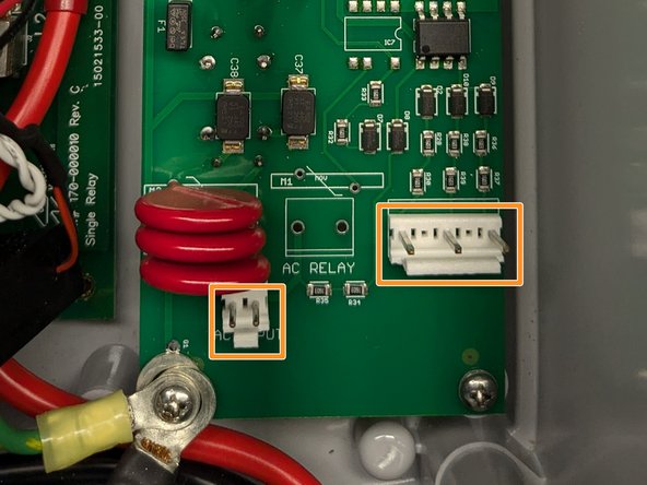
Connect AC_INPUT (RED and BLACK small 2 Position connector) and AC_TEST (RED and BLACK Large 3 Position connector)
-
-
-
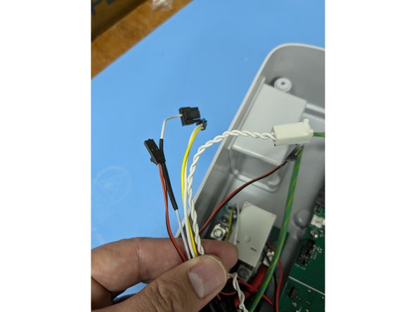
Gather the rest of the wires together and route up and along the green wire. Loosely add a couple tie wraps to keep the wires away from the RED and BLACK power wires.
-
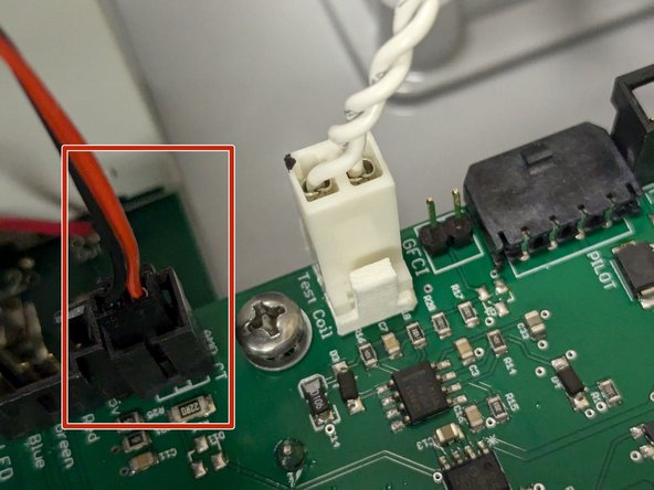
Connect the donut shaped coil WITHOUT the additional wire wrap to the AMP_CT connector.
-
Note - One Power wire runs through this coil.
-
-
-
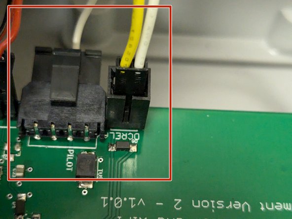
Connect the connector that goes to the relay to the DCRELAY connector and the pilot wire that goes out to the EV Handle to the PILOT connector.
-
Connect the Donut shaped coil WITH the additional wire wrap to the GFCI connector. Connect the Wire Wrap to the TEST_COIL connector.
-
Note - Two power wires go through the GFCI coil.
-
-
-
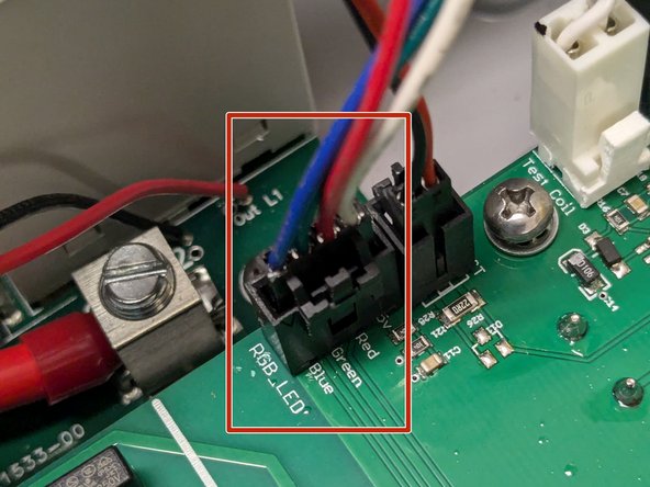
Connect the cable for the indicator lights to the RGB_LED connector.
-
Secure the lid with the 4 Phillips head screws
-


Cancel: I did not complete this guide.
8 other people completed this guide.
Attached Documents
31 Comments
I have searched for the answer but I am not seeing it. Once I have purchased and installed the replacement board in the Juice box then what? What software/web page etc. do we use to connect to it? Thanks
Pat Cosgrove - Open Reply
To connect to your station you use any device with WiFi and a Web browser. All control is local, no cloud or apps needed.
The board comes with a Quick Start Guide that has an overview. A full guide for WiFi setup is here: WiFi - Join Network
I Installed new chip/board and when I finished installation the I get a "solid green" light. I completed the system startup however when I plug our car into the charger I get an error message from the car saying "no power detected". There is no click from the relay to attempt to start charging.
The only thing I see is in the "monitoring tab" under safety I have a "no ground" with 7 counts. I've double checked the wiring in the box and I'm fairly certain I wired everything correctly especially with the big green wire. The previous Juicebox worked fine for years with no problems until I disconnected it. I know the wiring in the wall is good, and that I have a ground back to the panel (our house is only 9 years old) and I hired an electrician to do the initial install (it was not a DIY home project). Any help troubleshooting this would be appreciated, I'm at a point where if I can't figure it out I'm going to put the old chip back in as we need our high voltage charger back online.
jon parrish - Open Reply
I just solved a similar v2 conversion issue - sharing in case it helps.
Symptoms: Green light, WiFi working, no errors, but car wouldn't charge. No relay click. 0V at pilot pin + ground.
Root cause: Single green ground wire (Step 3) was in the wrong screw position. "Top left" is ambiguous depending on board orientation.
Fix: Moved the green wire to the correct corner. Immediately got 11.3V on pilot, relay clicked, now charging happily.
Tip: If you have these symptoms, measure DC voltage from pilot pin to ground at the J1772 plug. Should see ~12V. If 0V, check that ground wire location.
Edit/follow up. I used Google Gemini AI to trouble shoot the problem. It recommended I add a ground wire in the far right port of the "pilot connector" (shown in step 6). I then put the other end of the wire under the 3 green wires in the bottom left screw (shown in step 3). This allowed the pilot wire to detect the ground. Hope this helps anyone else who runs into this error, took me about 3 hours to figure out, not sure why my install required this/was unique.