Tools
Parts
-
-
Strip one-half inch of each other three wires on the connector cable
-
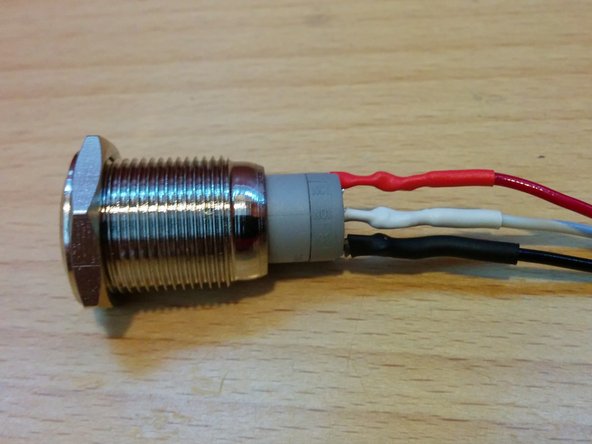
Separate insulation on wires and place heat shrink tubing over the corresponding color.
-
-
-
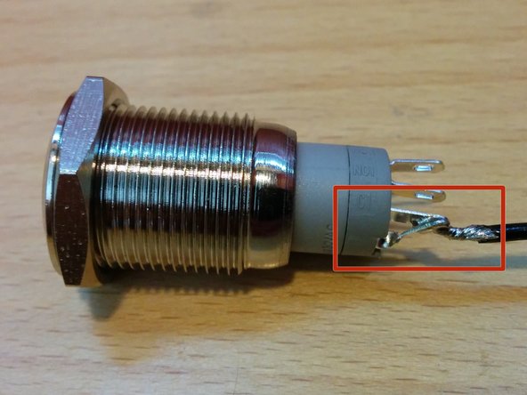
Solder the ground wire to BOTH the negative "-" terminal and the neighboring terminal labeled "C1".
-
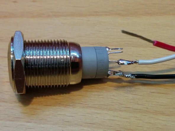
Solder the white wire to the middle terminal labeled in "NO1".
-
Solder the red wire to the positive terminal at the end of the row labeled "+" and shrink the tubing over the connections on all three wires.
-
The unused terminal labled "NC1" on the button may be clipped off if desired.
-
Cancel: I did not complete this guide.
17 other people completed this guide.
4 Comments
My unit never shipped with a button.
It was recommeded to me that I could use any similar button to do this. At minimum it can be a SPST, but I found that most switches are DPDT. The momentary contact needs to be between the signal (white) and ground (black). The positive (red) does not need to be connected, but is useful if you want the button to be lit.
The connector pictured here is a 3 pin servo lead, however, more recent versions of Openevse seems to use a different type of 3 pin connector (looks like JST type). I shaved off the edges of the servo lead so it fit into the connector.
what type switch is it? momentary contact or push on push off? spst or dpst? etc.
tom cowley - Resolved on Release Reply
Pish button is to enter configuration menu, set timers, add xxx kWh, charge for xxx minutes, etc.
Christopher Howell - Resolved on Release Reply
What is the application of the push button? To turn the EVSE off completely and prevent a phantom power draw?
fujioutland - Resolved on Release Reply


