Tools
Parts
-
-
Carefully remove all the components from the anti-static bag.
-
-
-
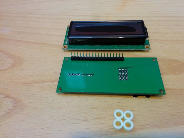
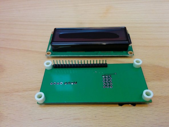
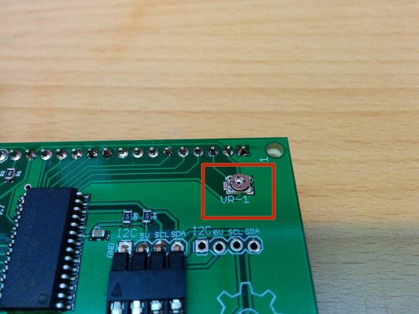
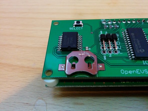
Solder the 16 (Mono LCD) or 18 (RGB LCD) pin header on the bottom of OpenEVSE logic board (solder from the top - pins on bottom) See picture 1 and 2.
-
Do not install header pins in the G & B holes if you are building a Mono LCD.
-
-
-
Place nylon spacers on each corner of the logic board.
-
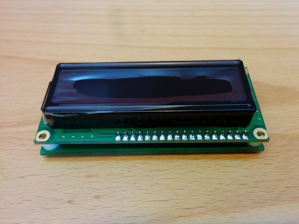
Position LCD module on top of the spacers and solder in place.
-
-
-
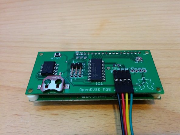
Connect 4 pin cable to the logic board with ground on the left side. Cable colors may vary.
-
Adjust contrast with VR-1 pot.
-
Optional - Insert a CR1216 or CR1220 coin cell battery if you wish to keep current time after power failure with the Real Time Clock option.
-
-
-
Connect 4 pin LCD cable to the OpenEVSE board.
-
Ground pin is closest to board edge.
-
Cancel: I did not complete this guide.
14 other people completed this guide.
8 Comments
The brigthness does not adjust. No idea whether I broke the V1-pot or that it was already broken. Can this pot be replaced?
The contrast adjustment is very fine, too much or too little and you will not see text. The proper spot is about 1/4 turn CW from the CCW stop.
If the pot spins freely and does not stop or has broken off it can be replaced. Contact support at openevse dot com
My board came assembled, the board on top of the LCD is smaller and the only problem is that the cable from the switch are too short I had to bend the connectors on the switch, this cable need to be half inch longer.
Also the Screws don't fit through RGB board and 1/8 inch too long.
The supplied large header has 20 pins. Cut off two to make 18. Initially thought I must have the monochrome since header was two pins larger.
Step three would be better to tack solder end pins to hold in place. Then assemble the spacers and other board per step 4 to keep all the pins aligned while soldering step 3. Separate, inspect, then do step 4.
Scott, The Monochrome LCD only has 16 pins. The logic board is universal for both LCD types and has 18 pins to accept either the 18 pin RGB LCD or the 16 pin Monochrome LCD. During assembly do not solder pins in position 17 or 18 labeled "G" and "B" and circled with silk screened print. If pins 17 and 18 are already soldered they can be clipped.
Christopher Howell - Resolved on Release Reply


