Difficulty
Moderate
Steps
12
Time Required
02:00:00 - 03:00:00
- OpenEVSE 30A Charging Station 12 steps

Featured Guide
This guide has been found to be exceptionally cool by the site's staff.
Quiz
0
Introduction
- Warning Assembly of a Electric Vehicle charging station requires wiring Alternating Current (AC) components that will be exposed to voltages from 100 to 250v. If you do not have the experience and knowledge required to safely work with AC voltages please consult with an experienced electrician for assistance and inspection of your work.
- Note Regularly inspect your charging station. Pay special attention to excess heat, components, handles, and wiring will be warm but they should not be HOT...
- Always Disconnect your charging station from power before performing an inspection and/or maintenance
Tools
No tools specified.
-
-
If you ordered the "Quick Kit" you will need to build the Button, GFCI coil, LCD and OpenEVSE PLUS.
-
-
-
-
-
-
-
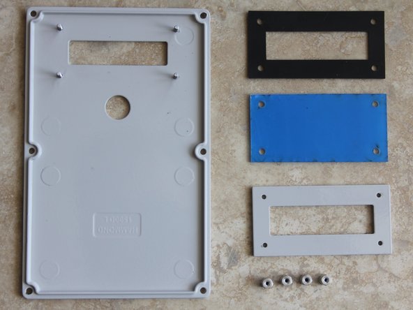
Place Enclosure lid on a soft surface, use care not to damage or scratch the enclosure finish. Remove HEX standoffs from the lid.
-
Clean the laser cut LCD seal and enclosure surface to ensure a proper water tight seal.
-
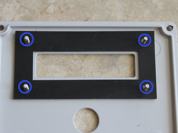
Place Seal over fasteners
-
Peel the protective covering from the laser cut clear acrylic window. Ensure the window is clean. Place over fasteners on top of the seal.
-
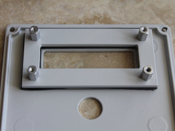
Place the machined pressure plate on top of the LCD. Replace all 4 HEX standoffs loosely.
-
IMPORTANT- evenly apply pressure to the sandwich alternating in a X pattern (Top Left - Bottom Right - Bottom Left - Top right) slowly until the Seal begins to enlarge.
-
Test seal by pouring water on the front side of the LCD window. If water leaks to the back side adjust seal pressure.
-
-
-
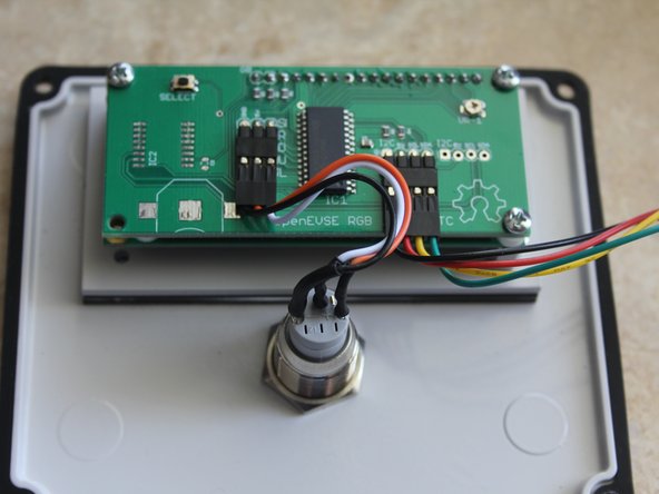
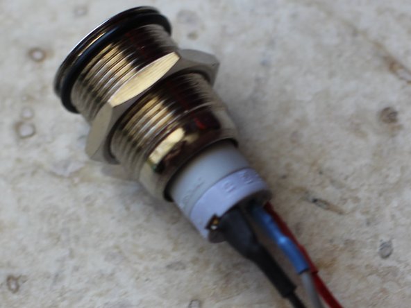
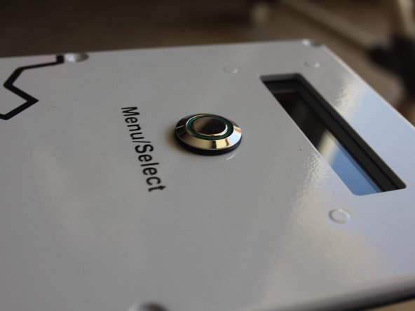
Mount the water resistant button switch to the enclosure lid. Seal should be placed on the outside. Tighten until seal expands.
-
Do not over tighten seal, if squeezes out of place the button is too tight.
-
Test enclosure lid again for water tightness. Spray water around the LCD window and button and ensure water does nor leak to the back side of the lid. Adjust as necessary.
-
Using 4 - 1/2" screws. Mount built LCD module to the lid. Place nylon spacers between the logic board and LCD.
-
Screws should be secure. Take care not to over tighten.
-
-
-
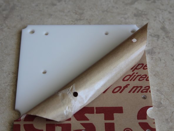
Peel protective coating from the mounting plate.
-
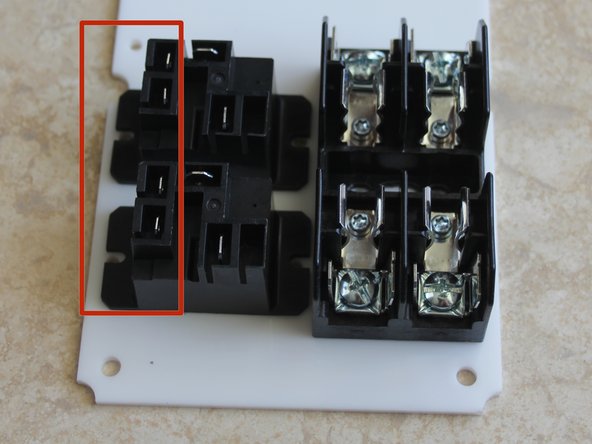
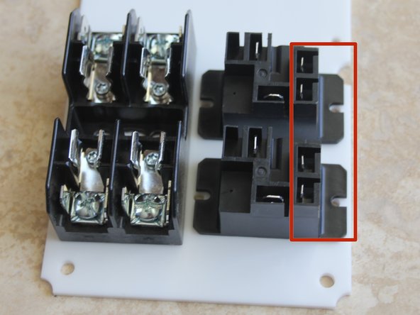
Your Charging station can be built with AC input Left and J1772 Right or opposite. Flip mounting plate to desired position. Fuses will line up with AC input and relays J1772 cable.
-
Mount fuse block with 2 - 3/8" screws from the top and lock nuts on the bottom.
-
Position relays so the small tabs are to the outside for easier routing of low voltage wires.
-
Mount Relays with 2 - 3/8" screws from the top and lock nuts on the bottom.
-
-
-
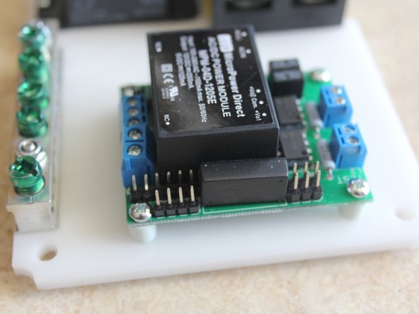
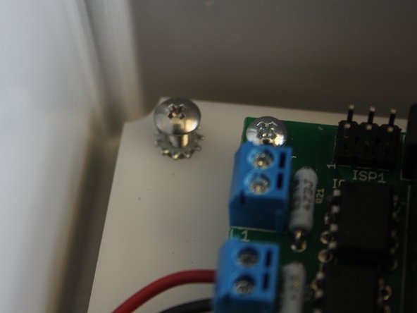
Mount OpenEVSE Plus board with 5/8" screws from the top.
-
Place nylon spacers between OpenEVSE board and mounting plate. Tighten Lock Nuts from the bottom. Do not over tighten.
-
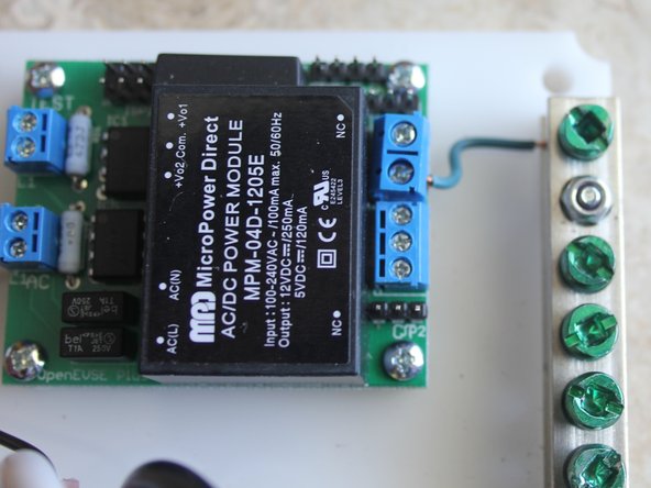
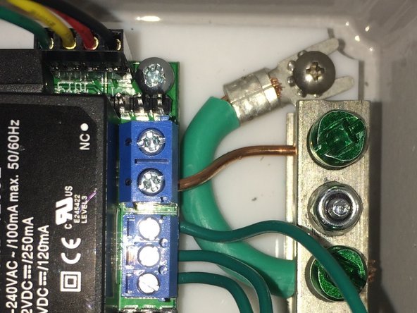
Mount Ground block with 2 - 3/4" screws from the bottom. Tighten Lock nuts from the top.
-
Connect OpenEVSE Ground to the ground Block. Ensure connections are secure.
-
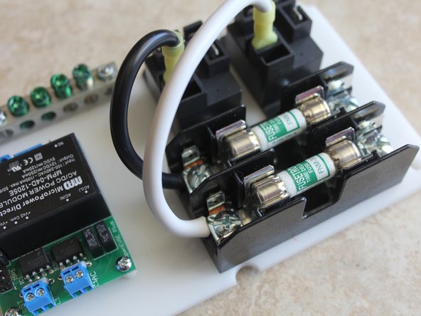
Crimp Yellow connector to 10AWG wire. Screw to the Fuse block. Wire can come from excess from AC cord or J1772 cable.
-
Ensure crimps are secure. Do not solder connectors designed for crimping. Do not connect and disconnect terminal. If loose, discolored, or damaged replace immediately.
-
-
-
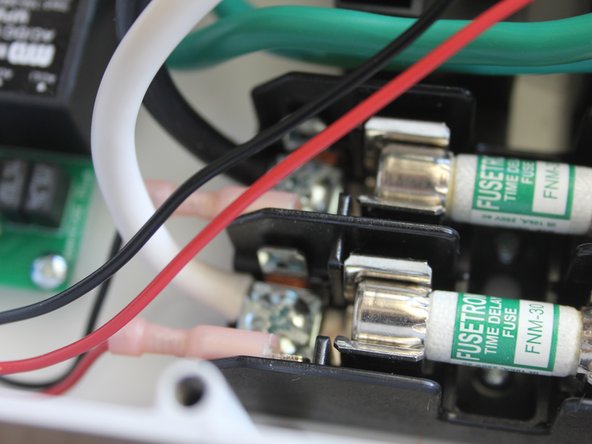
Crimp 22AWG wire to larger 1/4" pink QC connectors. Connect to Fuse block QC terminals.
-
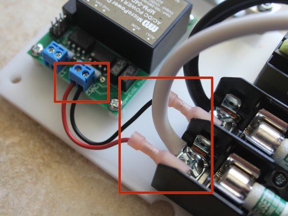
Screw the 22AWG wires to the AC line block on the OpenEVSE board.
-
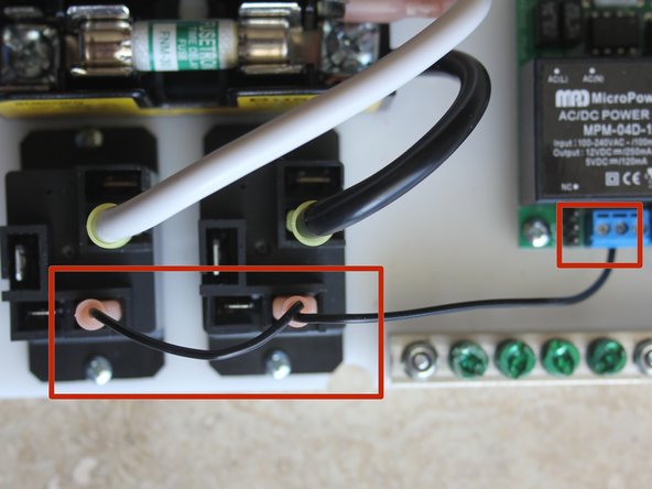
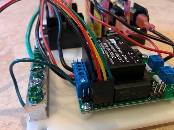
Connect OpenEVSE common relay output (center pin) to 1 relay coil terminal on each relay using small pink QC connectors.
-
Connect OpenEVSE controller Relay 1 output to remaining pin on first Relay.
-
Connect OpenEVSE controller screw terminal Relay output 2 to remaining pin on second relay.
-
-
-
Mount Plate into enclosure base with 3 of the 4 wide head 3/8" screw and lock washer. Do not install screw in the hole closest to the ground block.
-
Crimp spade connector to the Green 10 AWG wire. Secure to enclosure base with the remaining 3/8" wide head screw and lock washer.
-
Connect Enclosure base ground wire to the ground block.
-
-
-
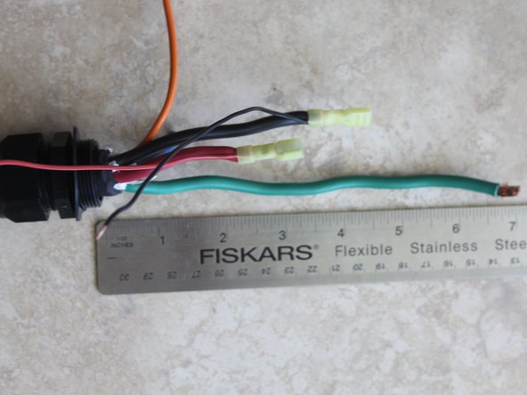
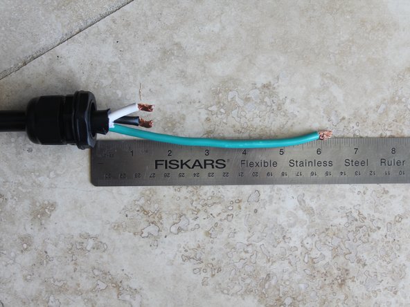
Prepare J1772 cable. Strip Cable back at least 8". Put Cable Gland on cable, it may take some effort depending on the diameter of the cable.
-
Ground and Pilot conductors should be 7" - 8" long.
-
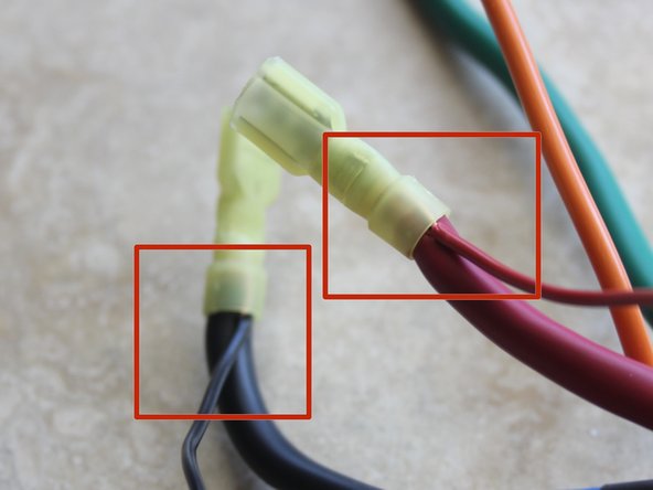
One Hot conductors should be about 5" long and the other slightly shorter. Crimp Yellow QC connectors to the Hot Conductors AND a 22AWG wire for the AC Test connections.
-
Ensure crimps are secure. Do not solder connectors designed for crimping. Do not connect and disconnect terminal. If loose, discolored, or damaged replace immediately.
-
-
-
Prepare AC cable (if Applicable). Strip back outer insulation 7". Put Cable Gland on cable.
-
Ground conductor should be 6" - 7" long.
-
Hot conductors should be 2" long.
-
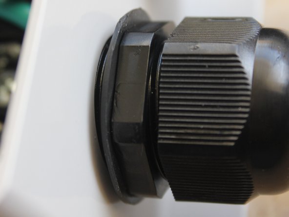
Secure AC Cord Cable Gland to enclosure on the side with the fuse block.
-
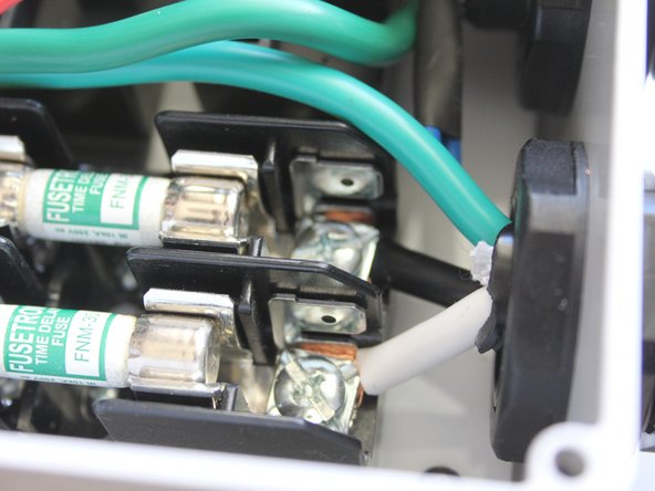
Connect Hot Wires to the fuse block.
-
-
-
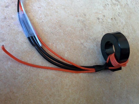
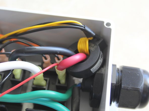
Temporarily tape the 3 wires from the connector to coil leads with about 3/4" overlap.
-
Wrap self test wire through coil 5 times.
-
Secure with shrink wrap tubing as close to the GFCI coil as possible.
-
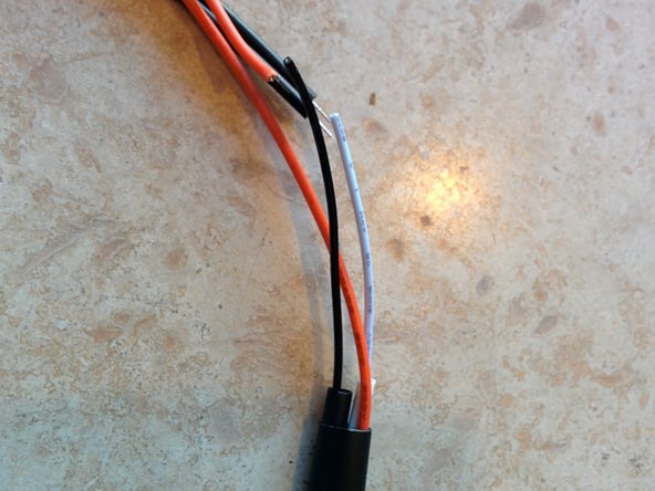
Cut wires to length with 1/4" overlap. Solder white wire to 1 lead of the GFCI coil. Shrink tubing over the solder joint.
-
Solder BOTH the Orange self test lead AND the second GFCI coil lead to the black wire (Ground).
-
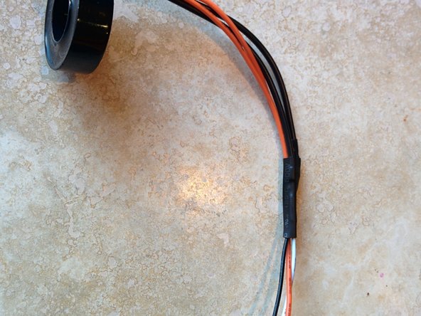
Shrink tubing over the wires.
-
-
-
Connect J1772 cable gland to the enclosure base.
-
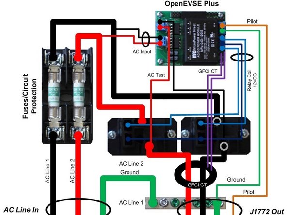
Run both HOT lines through the GFCI coil.
-
Connect J1772 Hot lines to relay outputs.
-
Connect the AC Test leads to the OpenEVSE board.
-
Connect J1772 Ground to Ground block
-
-
-
Connect 4 pin LCD cable to the OpenEVSE board.
-