
Featured Document
-
-
Unplug your station or turn off the circuit breaker. Never work on your station energized.
-
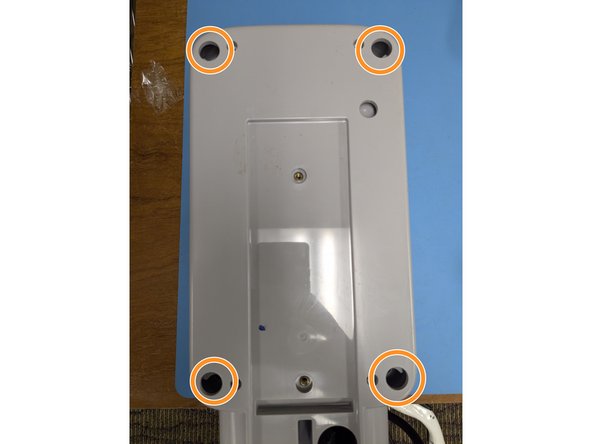
Remove the 4 Phillips head screws.
-
Carefully lift the lid and disconnect the cable for the indicator lights.
-
-
-
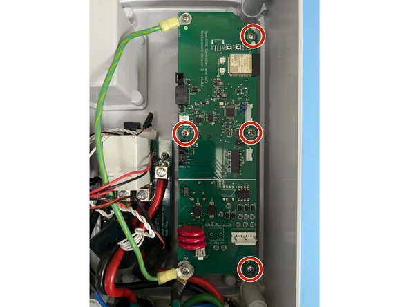
Remove the 6 Phillips head screws on the controller board.
-
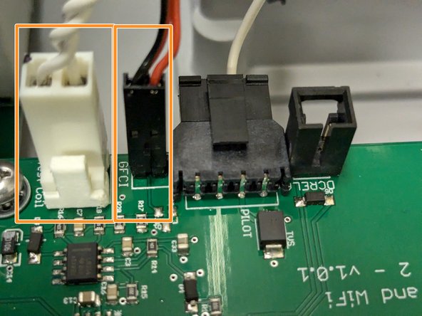
Remove all the connectors. Note most have tabs which when pressed release the connector.
-
Remove the circuit board.
-
-
-
Install the OpenEVSE controller.
-
Secure with the 6 Phillips screws removed in the previous step.
-
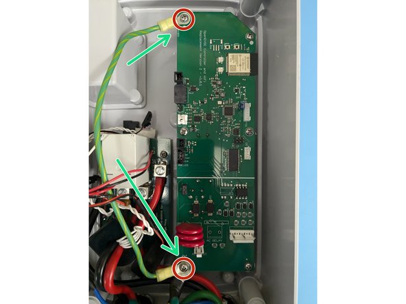
Add the single green wire under the top left position.
-
Add all 3 green wires under the bottom left position with the longest screw.
-
-
-
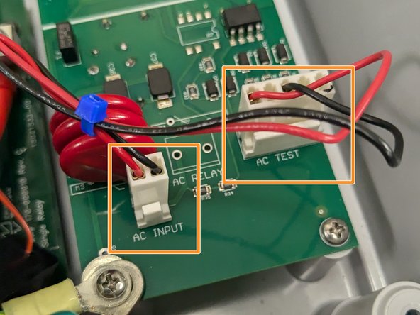
Identify the AC wires coming from the circuit board/relay module. Tie wrap them together.
-
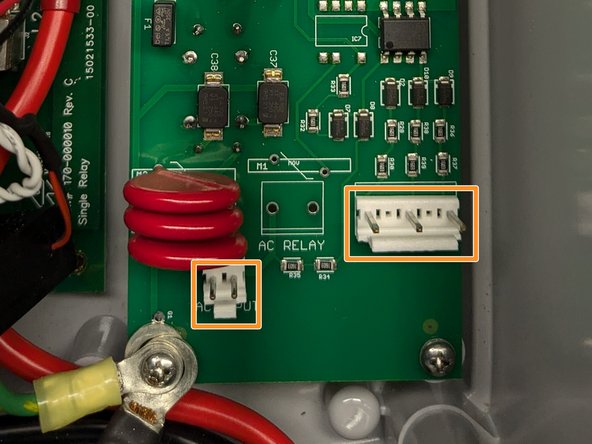
Connect AC_INPUT (RED and BLACK small 2 Position connector) and AC_TEST (RED and BLACK Large 3 Position connector)
-
-
-
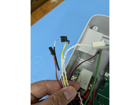
Gather the rest of the wires together and route up and along the green wire. Loosely add a couple tie wraps to keep the wires away from the RED and BLACK power wires.
-
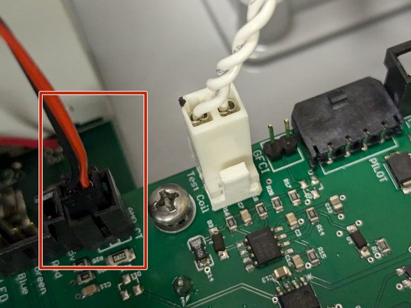
Connect the donut shaped coil WITHOUT the additional wire wrap to the AMP_CT connector.
-
Note - One Power wire runs through this coil.
-
-
-
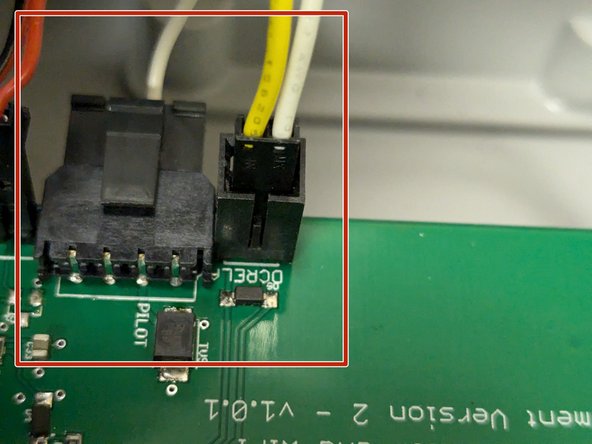
Connect the connector that goes to the relay to the DCRELAY connector and the pilot wire that goes out to the EV Handle to the PILOT connector.
-
Connect the Donut shaped coil WITH the additional wire wrap to the GFCI connector. Connect the Wire Wrap to the TEST_COIL connector.
-
Note - Two power wires go through the GFCI coil.
Working with an older juicebox 2. The wire that should go to the pilot connection has to be spliced. I'm not sure the old connector, but the wire is 16AWG so it won't fit in the molex connector in the kit without a step down on wire size.
Connector says D2 on top left, MXN on top right, 55 57 across the depressor tab. If that helps at all
-
-
-
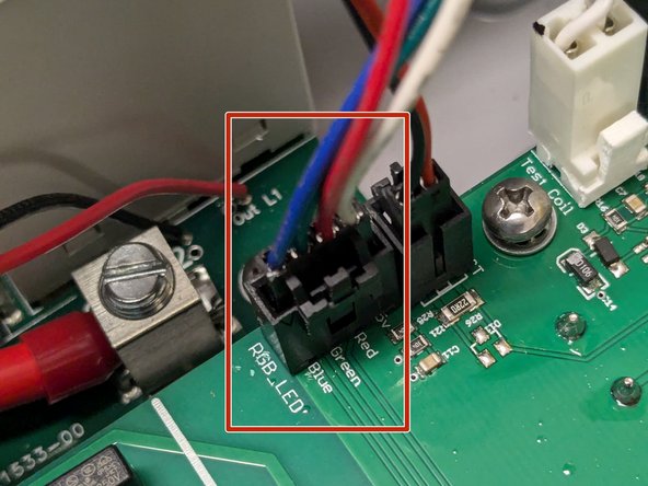
Connect the cable for the indicator lights to the RGB_LED connector.
-
Secure the lid with the 4 Phillips head screws
-


Cancel: I did not complete this guide.
8 other people completed this guide.
Attached Documents
31 Comments
I have searched for the answer but I am not seeing it. Once I have purchased and installed the replacement board in the Juice box then what? What software/web page etc. do we use to connect to it? Thanks
Pat Cosgrove - Open Reply
To connect to your station you use any device with WiFi and a Web browser. All control is local, no cloud or apps needed.
The board comes with a Quick Start Guide that has an overview. A full guide for WiFi setup is here: WiFi - Join Network
I Installed new chip/board and when I finished installation the I get a "solid green" light. I completed the system startup however when I plug our car into the charger I get an error message from the car saying "no power detected". There is no click from the relay to attempt to start charging.
The only thing I see is in the "monitoring tab" under safety I have a "no ground" with 7 counts. I've double checked the wiring in the box and I'm fairly certain I wired everything correctly especially with the big green wire. The previous Juicebox worked fine for years with no problems until I disconnected it. I know the wiring in the wall is good, and that I have a ground back to the panel (our house is only 9 years old) and I hired an electrician to do the initial install (it was not a DIY home project). Any help troubleshooting this would be appreciated, I'm at a point where if I can't figure it out I'm going to put the old chip back in as we need our high voltage charger back online.
jon parrish - Open Reply
I just solved a similar v2 conversion issue - sharing in case it helps.
Symptoms: Green light, WiFi working, no errors, but car wouldn't charge. No relay click. 0V at pilot pin + ground.
Root cause: Single green ground wire (Step 3) was in the wrong screw position. "Top left" is ambiguous depending on board orientation.
Fix: Moved the green wire to the correct corner. Immediately got 11.3V on pilot, relay clicked, now charging happily.
Tip: If you have these symptoms, measure DC voltage from pilot pin to ground at the J1772 plug. Should see ~12V. If 0V, check that ground wire location.
Edit/follow up. I used Google Gemini AI to trouble shoot the problem. It recommended I add a ground wire in the far right port of the "pilot connector" (shown in step 6). I then put the other end of the wire under the 3 green wires in the bottom left screw (shown in step 3). This allowed the pilot wire to detect the ground. Hope this helps anyone else who runs into this error, took me about 3 hours to figure out, not sure why my install required this/was unique.
can this be used with the contactor you sell to repair a juicebox v2 with a stuck contactor? my EX90 GHCA failed and destroyed the contactor when it did.
Nick Horvath - Open Reply
I have installed this board last night and kept getting GFCI Self Test Fails... then with self test off, I got GFCI fail when plugging in car. Today I have checked the wiring and connections (reseeded and re did the ties). I still have the same error. Any suggestions on how to get past my GFCI issues?
Jeff Osborn - Open Reply
The GFCI coil is likely plugged into the AMP position and the AMP coil plugged into the GFCi position. The JuiceBox engineers used the same connector for both so it is easy to plug into the wrong connector.
This guide was perfect! It accurately described the steps needed to replace the original Juicebox v2 board.
Thank you!
Michael Dion - Open Reply
Hello, is this board compatible with the Juicebox v2 48A?
The same plugs, etc., and the same board as the 32/40A to
Thank and advance
Sebastien
Sebastien bonhomme - Open Reply
@bonhomme101 The replacement board is not limited to a particular current. It can be set to any valid SAE J1772 current (6A - 80A). So yes it can be used for a Juicebox 48A.
Does this replacement board also work on the European 3 phase version?
(My board is broken, and even if I can use just one phase it would be a great upgrade for me)
Rafael Levy - Open Reply
The white wire wound a couple of times around that one thick coil is definitely referred to as "wrapped" in this guide. If I recall correctly, there is also a pair of red and black wires wrapped around (or through) that coil. A different coil right next to that has only the red and black wires wrapped around/through it.
No doubt John has completed his project, but perhaps someone else will have the same question.
Does this support the RFID reader in the commercial versions? We use this heavily.
Mark McDonald - Open Reply
Can you set the maximum station output current via a jumper? My car can only pull 3.8kW and I get it that under normal working conditions the station can't supply more than the car can accept but I am a little paranoid about the maximum current value resetting to a higher default value after the station is power cycled. If I do change the value in the web interface, can I set it in the ESP32's flash?
I upgraded my non-functioning JuiceBox V2 yesterday using both this OpenEVSE tutorial and this Youtube tutorial, which was useful but a bit unnerving as the youtuber got it wrong on the first try and never explains his mistake. In my caution, I labeled each wire as I disconnected it, first finding it in OpenEVSE tutorial using supplied pictures and text, then affixing a label matching the correct position on the OpenEVSE board. There are three same-sized plugs that you could mix up if not careful. My labels made it easy to get it right; the station is working perfectly! This is a great example of "reuse, repair, recycle"! Much of the JuiceBox is retained and reused, including all that copper, plastic case and fittings, beefy handle, etc. All that gets recycled is the old board. Thank you OpenEVSE and Chris Howell! Please consider making a specifications label that can replace the Enel X label, and a big OpenEVSE label to cover the word JuiceBox! --Jeff Parker
Jeffrey Parker - Open Reply
I’ve realised that my juice box works as single or 3-phase. It has a separate relay for disconnection the neutral and the three phases go through the contactor.
I can remove two phases and their CTs and put the neutral onto the contactor if nobody see issue with that. The GF CT has four wires which I assume 2 for supply/signal and two for the looped wire or should just use a spare-phase CT and wrap a separate wire 5 times as other instructions?
Would that get it working?
Daren keates - Open Reply
I’ve just come to Connect this up and the instructions don’t match the wire colour or some connector sizes. The Test coil has a four way connector on the end but the pub is only 2-wire. I’ve got loads left over too. Help, in on peices and I’m without power.
Daren keates - Open Reply
I'm not familiar with "wire wrap" designation. Does this refer to multi-conductor cables? In the photos, is this the white twisted pair cable and red/black dual conductor cables?
John Poldoian - Open Reply
The white wire wound a couple of times around that one thick coil is definitely referred to as "wrapped" in this guide. If I recall correctly, there is also a pair of red and black wires wrapped around (or through) that coil. A different coil right next to that has only the red and black wires wrapped around/through it.
No doubt John has completed his project, but perhaps someone else will have the same question.
Early JuiceBox v2 used different header/plug on blue pilot wire - it's spliced in these pics. $6 ebay Micro-Fit 3.0 4-pin FTW (plug looks male, but its pins are female, require 20-24 AWG).
Tom Werner - Resolved on Release Reply
Realized my comment on the earlier step is a better reply down here:
Working with an older juicebox 2. The wire that should go to the pilot connection has to be spliced. I'm not sure the old connector, but the wire is 16AWG so it won't fit in the molex connector in the kit without a step down on wire size.
Connector says D2 on top left, MXN on top right, 55 57 across the depressor tab. If that helps at all.
Jared -
The connector in the photos/guide is Molex Micro-Fit 3.0 43650 Part 0436500400. Mating plug is is Micro-Fit 3.0 43645 Part 0436450400. Do you know the type of connector on the early v2s?
Is there a guide to change OCPP end point after the controller is replaced?
@kishoredvrs Here is a OCPP guide for Pulse Energy OCPP setup. The process is similar for any provider.
Step 0: Remove your Juicebox from the wall. You are smart enough to unplug or disable the circuit breaker before you do this, right?
I needed to push my Juicebox straight up to release the screws from the top of the slots holding them in place. If you have a lock, turn the key to the vertical position, then slide the entire controller and cable hook upwards a few centimeters. In them first picture below, the key is in the unlock position. You can see two screws on the top device, which is the controller, that are on the centerline, and two screws on the bottom device, on the back of the cable hook, which are aligned horizontally.
The connectors are not in the same position on the openevse controller as they are on the ENEL. To remember where those connectors were, I took a high resolution picture before I began detaching wires.
Jim Black - Open Reply