Difficulty
Moderate
Steps
6
Time Required
- Testing Basic and Advanced 6 steps

In Progress
This guide is currently being written. Reload periodically to see the latest changes.

Private
This guide will not appear in search results and can only be viewed by team members!
Quiz
0
-
-
Testing is an important part of the OpenEVSE build process. This guide provides testing recommendation both for the user and those developing hardware and software.
-
OpenEVSE performs extensive self test during boot, before closing relays/contactors and while operating.
-
Basic Testing is recommended for all builders after building your charging station and whenever maintenance is performed.
-
Advanced testing shall be performed by hardware and software developers before releasing "Stable" firmware or a new hardware revision.
-
For builders wishing to better understand how a charging stations work, Advanced Testing may be performed.
-
Advanced Tests require live AC Power. Use extreme caution when working near energized high voltage components.
-
-
-
During the boot process OpenEVSE will run a Power on Self Test (POST).
-
If the POST fails by indicating any Error condition or a RED LED/LCD please refer to the Troubleshooting guide before proceeding.
-
-
-
EVSE states can be tested with a few resistors and a diode, and EV Simulator or an EVSE Tester.
-
-
-
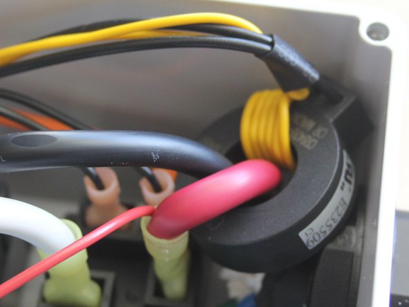
Power on OpenEVSE Charging Station with the GFCI coil with self test loop disconnected.
-
The OpenEVSE Charging Station should fail the boot process with "Error GFCI Self Test Failed" and indicate red on the LED/LCD.
-
If the Power on Self Test deos not fail with the coils disconnected, check that GFCI Self Test is enabled in the Service Menu.
-
If GFCI self check is enabled and the test does not fail please refer to the Troubleshooting guide.
-
-
-
The following tests are intended for Hardware and Software developers to validate hardware revisions and validate production software.
-
Builders who wish to better understand the safety features of OpenEVSE Charging Stations may proceed if desired.
-
Advanced Tests require live AC Power. Use extreme caution when working near energized high voltage components.
-
-
-
GFCI must trip between 15ma and 20ma.
-
Using Ohms Law select to correct 5 watt resistors to draw 15ma and 20ma. Alternatively, a 5 watt resistor selected for 12ma plus a 5k 5w pot can be used to determine the exact trip point.
-
US - 120v line to ground 8k = 15ma and 6k = 20ma
-
Europe 230v line to ground 15.3k = 15ma and 11.5k = 20ma
-
While the EVSE is in State C "Charging" connect a wire with the 15ma resistor in parallel through the GFCI coil from one hot to ground. The Charging Station should not trip.
-
While the EVSE is in State C "Charging" connect a wire with the 20ma resistor in parallel through the GFCI coil from one hot to ground. The Charging Station should trip this time.
-