
-
-
Testing is an important part of the OpenEVSE build process. This guide provides testing recommendation both for the user and those developing hardware and software.
-
OpenEVSE performs extensive self test during boot, before closing relays/contactors and while operating.
-
Basic Testing is recommended for all builders after building your charging station and whenever maintenance is performed.
-
Advanced testing shall be performed by hardware and software developers before releasing "Stable" firmware or a new hardware revision.
-
For builders wishing to better understand how a charging stations work, Advanced Testing may be performed.
-
Advanced Tests require live AC Power. Use extreme caution when working near energized high voltage components.
-
-
-
During the boot process OpenEVSE will run a Power on Self Test (POST).
-
If the POST fails by indicating any Error condition or a RED LED/LCD please refer to the Troubleshooting guide before proceeding.
-
-
-
EVSE states can be tested with a few resistors and a diode, and EV Simulator or an EVSE Tester. After a sucessful Power on Self Test OpenEVSE should enter State A - Ready and the LED/LCD should be Green.
-
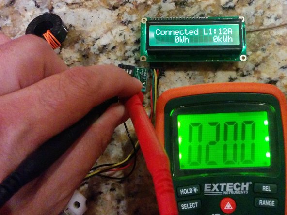
State B - EV Connected. Connect 2.74k resistance plus a diode from Pilot to ground. OpenEVSE display should display "EV Connected" and LED/LCD should turn Yellow. (OpenEVSE Sim - 1 on)
-
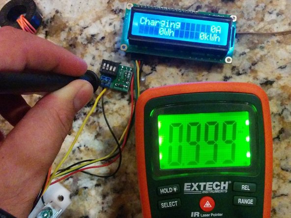
State C - Charging. Connect 882 ohm resistance plus a diode from Pilot to ground. OpenEVSE display should display "Charging" and LED/LCD should turn Blue. (OpenEVSE Sim - 1 on + 2 on)
-
State D - Ventilation Required. Connect 246 ohms resistance plus a diode from Pilot to ground. OpenEVSE display should display "EVSE ERROR - VENT REQUIRED" and LED/LCD should turn Red. (OpenEVSE Sim - 1 on + 2 on + 3 on)
-
-
-
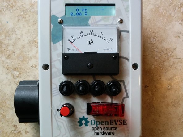
OpenEVSE outputs a 1000hz pilot signal when connected to an EV and Ready.
-
Using a Multimeter with frequency measurement, a oscilloscope or an EV Sim II from nslayer. Enter State B and measure frequency from pilot to ground.
-
Frequency should measure between 980 to 1020Hz.
-
Using a Multimeter with duty cycle measurement, a oscilloscope or an EV Sim II from nslayer. Enter State B and measure duty cycle from pilot to ground. Duty Cycle should match formulas below.
-
6 to 51A -- Amps = Duty cycle x 0.6 -- Duty cycle = Amps / 0.6
-
51 - 80A -- Amps = (Duty Cycle - 64) 2.5
-
-
-
Power on OpenEVSE Charging Station with the GFCI coil with self test loop disconnected.
-
The OpenEVSE Charging Station should fail the boot process with "Error GFCI Self Test Failed" and indicate red on the LED/LCD.
-
If the Power on Self Test does not fail with the coils disconnected, check that GFCI Self Test is enabled in the Service Menu.
-
If GFCI self check is enabled and the test does not fail please refer to the Troubleshooting guide.
-
-
-
The following tests are intended for Hardware and Software developers to validate hardware revisions and validate production software.
-
Builders who wish to better understand the safety features of OpenEVSE Charging Stations may proceed if desired.
-
Advanced Tests require live AC Power. Use extreme caution when working near energized high voltage components.
-
-
-
GFCI must trip between 15ma and 20ma.
-
Using Ohms Law select to correct 5 watt resistors to draw 15ma and 20ma. Alternatively, a 5 watt resistor selected for 12ma plus a 5k 5 watt pot can be used to determine the exact trip point.
-
US - 120v line to ground 8k = 15ma and 6k = 20ma
-
Europe 230v line to ground 15.3k = 15ma and 11.5k = 20ma
-
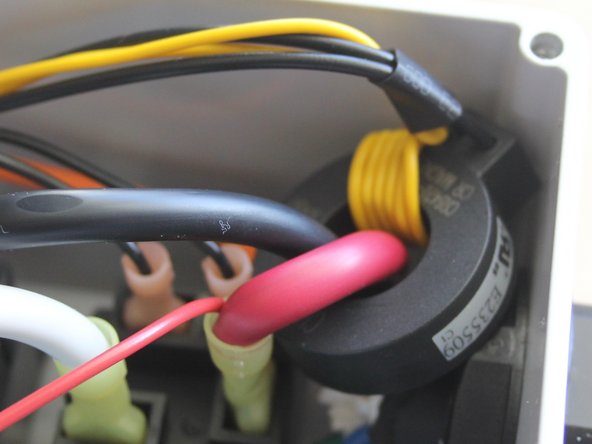
While the EVSE is in State C "Charging" connect a wire with the 15ma resistor in parallel through the GFCI coil from one hot to ground. The Charging Station should not trip.
-
While the EVSE is in State C "Charging" connect a wire with the 20ma resistor in parallel through the GFCI coil from one hot to ground. The Charging Station should trip this time.
-
-
-
OpenEVSE will recover and retry after a GFCI fault. The time to retrys is configurable in the OpenEVSE firmware.
-
Induce a GFCI Fault.
-
EVSE should display EVSE ERROR - GFCI FAULT.
-
Remove GFCI Fault. EVSE should recover after the time to retry has elapsed.
-
-
-
OpenEVSE will lockout if a GFCI fault occurs within 2 seconds of contact closure.
-
Enter State C (Charging).
-
Within 2 seconds of contact closure induce GFCI Fault. OpenEVSE should display SERVICE REQUIRED - GFCI Fault.
-
OpenEVSE will remain in this state until power is removed.
-
-
-
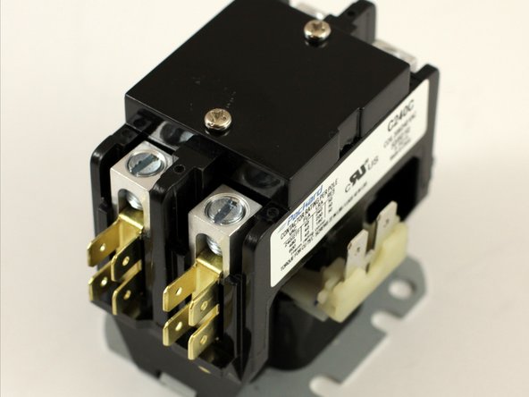
OpenEVSE tests the Contactor at each boot and every time before closing the contacts.
-
All OpenEVSE versions except v3 have 2 AC Detect chips. For v3 test just the hot connected to AC_TEST.
-
For testing on single phase 208 (US) and 230 (Europe) test just the Hot line. Neutral will not produce any results ad Neutral to ground should measure 0v.
-
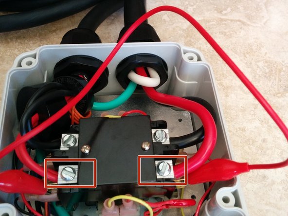
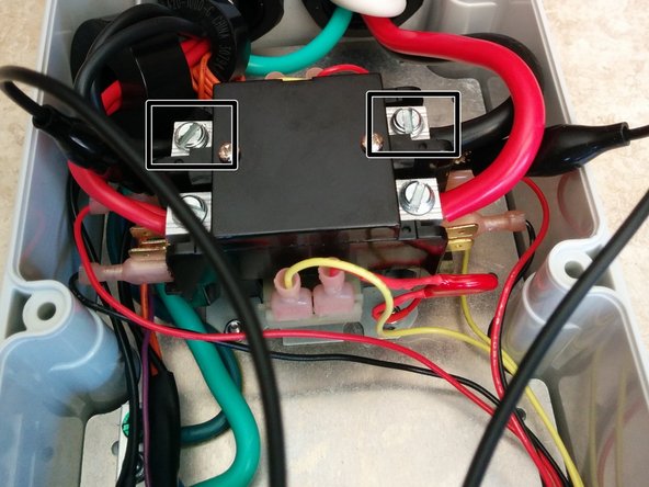
Testing Hot - Using a alligator clip connect across the relay from the line side of Hot 1 to the EV load side. Power on the Charging Station - The Charging should display "Error Stuck Relay".
-
Testing Hot 2 (US Split Phase) (Versions except v3) - Using a alligator clip connect across the relay from the line side of Hot 2 to the EV load side. Power on the Charging Station - The Charging should display "Error Stuck Relay".
-
-
-
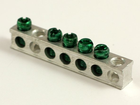
OpenEVSE checks for Earth Ground Continuously while Charging (State C).
-
Testing - Connect EV Simulator. Enter State C Charging. Disconnect Earth Ground from the OpenEVSE board. OpenEVSE should enter and Error state and Display "EVSE ERROR - NO GROUND".
-
Restore Ground Connection. EVSE should resume charging within 1 minute.
-


Cancel: I did not complete this guide.
11 other people completed this guide.