
-
-
Testing is an important part of the OpenEVSE build process. This guide provides testing recommendation both for the user and those developing hardware and software.
-
OpenEVSE performs extensive self test during boot, before closing relays/contactors and while operating.
-
Basic Testing is recommended for all builders after building your charging station and whenever maintenance is performed.
-
Advanced testing shall be performed by hardware and software developers before releasing "Stable" firmware or a new hardware revision.
-
For builders wishing to better understand how a charging stations work, Advanced Testing may be performed.
-
Advanced Tests require live AC Power. Use extreme caution when working near energized high voltage components.
-
-
-
During the boot process OpenEVSE will run a Power on Self Test (POST).
-
If the POST fails by indicating any Error condition or a RED LED/LCD please refer to the Troubleshooting guide before proceeding.
-
-
-
EVSE states can be tested with a few resistors and a diode, and EV Simulator or an EVSE Tester. After a sucessful Power on Self Test OpenEVSE should enter State A - Ready and the LED/LCD should be Green.
-
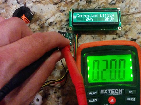
State B - EV Connected. Connect 2.74k resistance plus a diode from Pilot to ground. OpenEVSE display should display "EV Connected" and LED/LCD should turn Yellow. (OpenEVSE Sim - 1 on)
-
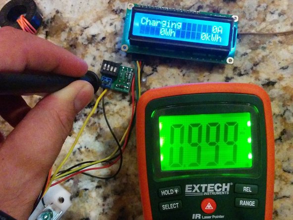
State C - Charging. Connect 882 ohm resistance plus a diode from Pilot to ground. OpenEVSE display should display "Charging" and LED/LCD should turn Blue. (OpenEVSE Sim - 1 on + 2 on)
-
State D - Ventilation Required. Connect 246 ohms resistance plus a diode from Pilot to ground. OpenEVSE display should display "EVSE ERROR - VENT REQUIRED" and LED/LCD should turn Red. (OpenEVSE Sim - 1 on + 2 on + 3 on)
-
-
-
OpenEVSE outputs a 1000hz pilot signal when connected to an EV and Ready.
-
Using a Multimeter with frequency measurement, a oscilloscope or an EV Sim II from nslayer. Enter State B and measure frequency from pilot to ground.
-
Frequency should measure between 980 to 1020Hz.
-
Using a Multimeter with duty cycle measurement, a oscilloscope or an EV Sim II from nslayer. Enter State B and measure duty cycle from pilot to ground. Duty Cycle should match formulas below.
-
6 to 51A -- Amps = Duty cycle x 0.6 -- Duty cycle = Amps / 0.6
-
51 - 80A -- Amps = (Duty Cycle - 64) 2.5
-
-
-
Power on OpenEVSE Charging Station with the GFCI coil with self test loop disconnected.
-
The OpenEVSE Charging Station should fail the boot process with "Error GFCI Self Test Failed" and indicate red on the LED/LCD.
-
If the Power on Self Test does not fail with the coils disconnected, check that GFCI Self Test is enabled in the Service Menu.
-
If GFCI self check is enabled and the test does not fail please refer to the Troubleshooting guide.
-
-
-
The following tests are intended for Hardware and Software developers to validate hardware revisions and validate production software.
-
Builders who wish to better understand the safety features of OpenEVSE Charging Stations may proceed if desired.
-
Advanced Tests require live AC Power. Use extreme caution when working near energized high voltage components.
-
-
-
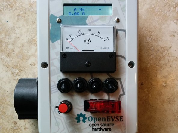
GFCI must trip between 15ma and 20ma.
-
Using Ohms Law select to correct 5 watt resistors to draw 15ma and 20ma. Alternatively, a 5 watt resistor selected for 12ma plus a 5k 5 watt pot can be used to determine the exact trip point.
-
US - 120v line to ground 8k = 15ma and 6k = 20ma
-
Europe 230v line to ground 15.3k = 15ma and 11.5k = 20ma
-
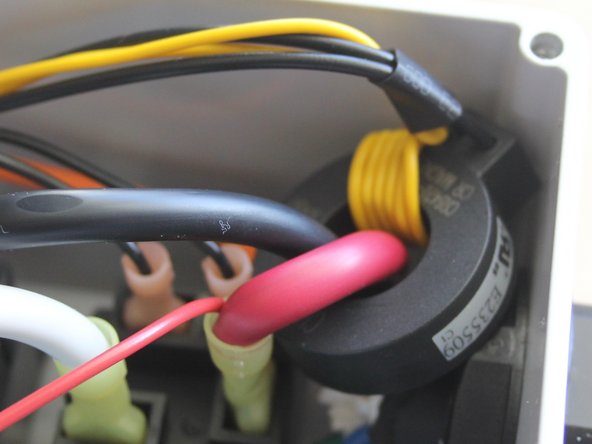
While the EVSE is in State C "Charging" connect a wire with the 15ma resistor in parallel through the GFCI coil from one hot to ground. The Charging Station should not trip.
-
While the EVSE is in State C "Charging" connect a wire with the 20ma resistor in parallel through the GFCI coil from one hot to ground. The Charging Station should trip this time.
-
-
-
OpenEVSE will recover and retry after a GFCI fault. The time to retrys is configurable in the OpenEVSE firmware.
-
Induce a GFCI Fault.
-
EVSE should display EVSE ERROR - GFCI FAULT.
-
Remove GFCI Fault. EVSE should recover after the time to retry has elapsed.
-
-
-
OpenEVSE will lockout if a GFCI fault occurs within 2 seconds of contact closure.
-
Enter State C (Charging).
-
Within 2 seconds of contact closure induce GFCI Fault. OpenEVSE should display SERVICE REQUIRED - GFCI Fault.
-
OpenEVSE will remain in this state until power is removed.
-
-
-
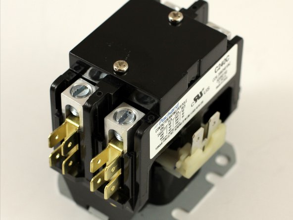
OpenEVSE tests the Contactor at each boot and every time before closing the contacts.
-
All OpenEVSE versions except v3 have 2 AC Detect chips. For v3 test just the hot connected to AC_TEST.
-
For testing on single phase 208 (US) and 230 (Europe) test just the Hot line. Neutral will not produce any results ad Neutral to ground should measure 0v.
-
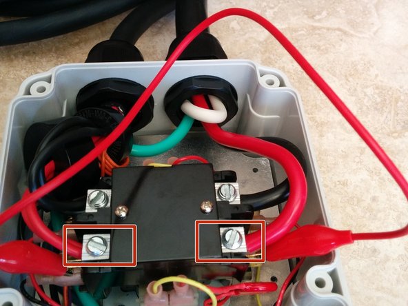
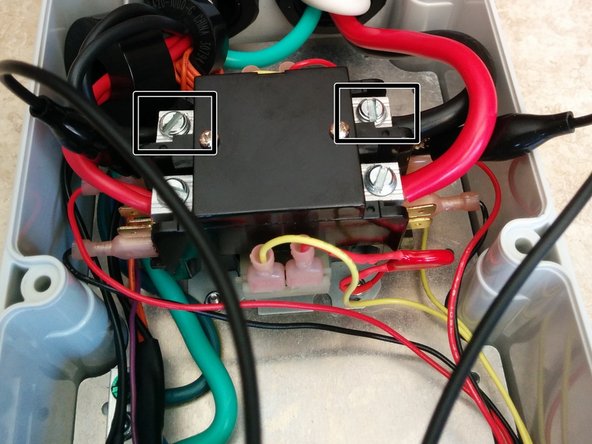
Testing Hot - Using a alligator clip connect across the relay from the line side of Hot 1 to the EV load side. Power on the Charging Station - The Charging should display "Error Stuck Relay".
-
Testing Hot 2 (US Split Phase) (Versions except v3) - Using a alligator clip connect across the relay from the line side of Hot 2 to the EV load side. Power on the Charging Station - The Charging should display "Error Stuck Relay".
-
-
-
OpenEVSE checks for Earth Ground Continuously while Charging (State C).
-
Testing - Connect EV Simulator. Enter State C Charging. Disconnect Earth Ground from the OpenEVSE board. OpenEVSE should enter and Error state and Display "EVSE ERROR - NO GROUND".
-
Restore Ground Connection. EVSE should resume charging within 1 minute.
@tuctrohs Split Phase Ground Monitoring while charging works on all Versions of OpenEVSE including v3. v3 boards (early 2014) were the only version with a single channel AC detect and could not autodetect L1 or L2 on split phase which is not a safety feature and not required by any standard.
The progression from v1 to v4 was very quick with only a few month between each, very limited numbers of each were sold. v4 (2014), v5 (2018), v5.5 (2021) and the current version v6.5.1 (2024) had several years between each.
The current version 6.5.1 does have two channels for AC Detect but like the v3 can not autodetect a single hot ot two hots on a split phase, this is due to the new UL requirement of "Continuous Ground Monitoring" vs the old standard of Ground Monitoring "while charging". Before we could use the same channel to watch fo AC from the load side of the relay when the relay was open it was used for stuck relay detection (verify no AC to ground) and "while charging" closed relay ground was good (verify AC to ground).
Christopher Howell - Open Reply
Sorry, I didn't look at V3 closely enough. V3 does not have the problem. It's just versions through 2.5 that have the problem. On split phase, with no ground, the monitoring circuit is perfectly symmetric. As a result, as with a voltage divider, the mid-point will sit exactly halfway between the phase legs. That means it is at ground potential even with no ground connection. Current will flow through the LEDs of both opto channels in series, without flowing through ground. That might not be immediately obvious, which is why I asked about testing. There are several people on the reddit thread who have simulated it, showing that it behaves the same with an without ground connected. Here's a link to one of those simulations running online.
It's great the that few shipped that way but having the documentation for the safety features show a non-working circuit doesn't inspire confidence in the project.
Tuctrohs -
Has anyone tried this on a 240 V split phase supply? There's a discussion on Reddit r/evcharging where people are saying it might not work--might not detect the fault.
Can you please explain what the Earth Ground test is actually testing? Thanks.
Paul Cooper - Resolved on Release Reply
Earth Ground testing verifies the ground path included the earth rod, electrical panel, circuit, socket/plug to the station. This is done by intensionally passing a very small current from each hot to ground.
It is possible to get a false positive if the relay is not operating property failing to close on command.
-


Cancel: I did not complete this guide.
11 other people completed this guide.