
Introduction
Warning Assembly of a Electric Vehicle charging station requires wiring Alternating Current (AC) components that will be exposed to voltages from 100 to 250v. If you do not have the experience and knowledge required to safely work with AC voltages please consult with an experienced electrician for assistance and inspection of your work.
Note Regularly inspect your charging station. Pay special attention to excess heat, components, handles, and wiring will be warm but they should not be HOT...
Always Disconnect your charging station from power before performing an inspection and/or maintenance
-
-
Remove any protective film from the clear window.
-
From the front place a 10mm screw through one of the small holes.
-
Flip the lid. Stack the foam window seal then clear window.
-
Thread a Hex Standoff onto the screw.
-
Repeat for the other 3 screws.
-
Tighten each screw/hex standoff to fully compress the foam.
-
-
-
Mount button with O-ring seal on the outside. Screw on the large hex nut from the inside.
-
Using 4 - 6mm screws. Mount display module to the lid.
-
Connect 4 pin connector to display module.
-
Note the color that represents Ground (Black as Pictured)
-
Connect the 3 position connector (2 wires attached) to the display module and the ends to the button.
-
-
-
If your kit contains a Struthers and Dunn relay, continue here. Guide
-
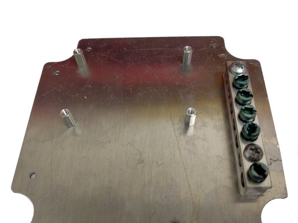
Position the plate with the 4 holes for the OpenEVSE controller up top and the Earth Ground bus bar on the right.
-
Mount hex standoffs to the top side of the plate with 6 mm screws.
-
Mount ground bar to the plate with 2 - 5/8" self threading screws.
-
Note: The screws from the ground bar packaging are not used.
-
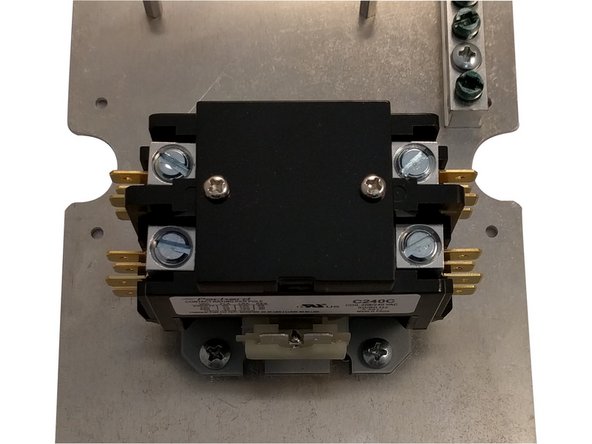
Mount the Packard relay using 4 - 1/4" self threading screws.
-
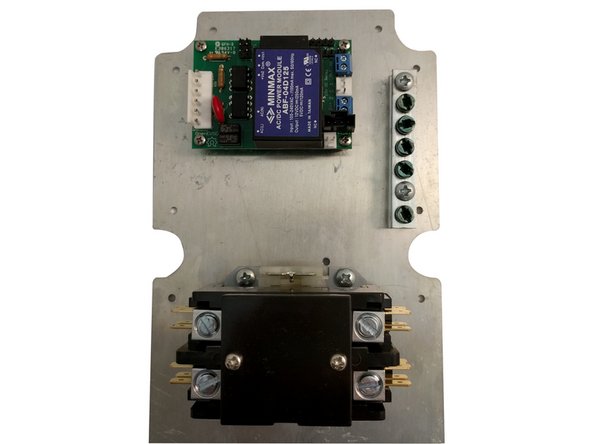
Mount OpenEVSE controller to the hex standoffs with 6mm screws.
-
-
-
These documents will assist with the steps that follow.
-
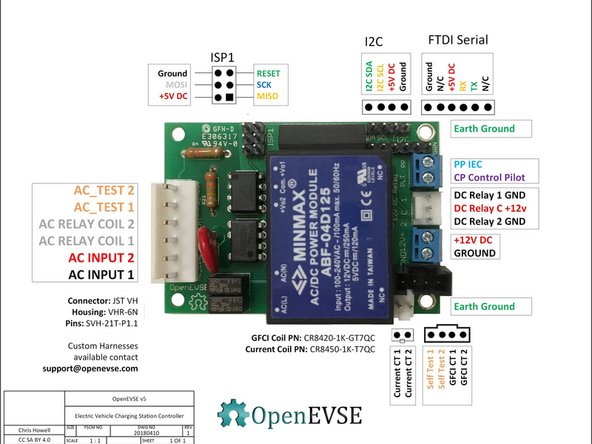
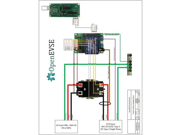
OpenEVSE Board Pins and Connections Download PDF
-
Advanced Series Schematic Diagram Download PDF
-
-
-
View OpenEVSE v5 Diagram in previous step for wires named below.
-
Connect the keyed wiring harnesses to OpenEVSE controller.
-
Wire colors may vary.
-
Connect AC INPUT 1 to the bottom left power terminal.
-
Connect AC INPUT 2 to the top left power terminal.
-
Connect AC_TEST 1 and 2 to the top and bottom right power terminals.
-
Connect AC_RELAY 1 and 2 to the top and bottom middle relay coil terminals.
-
Connect the keyed 4 pin GFCI coil to the OpenEVSE controller.
-
-
-
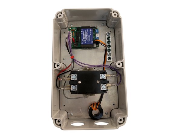
Mount plate to Enclosure box using 6 - self tapping screws (2 top, 2 middle 2 bottom).
-
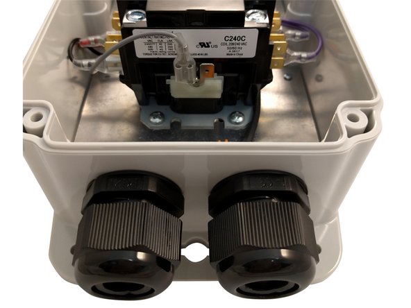
Install cable glands on the enclosure with seals on the outside.
-
-
-
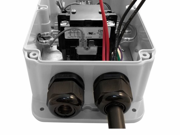
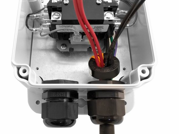
Insert EV Cable through the Cable Gland on the right and tighten.
-
Route the ground and pilot wires low in the enclosure up the right side.
-
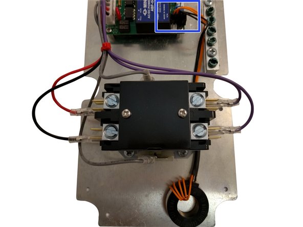
Thread only the hot and neutral AC lines through the 4 wire GFCI coil with the orange self test loop.
-
-
-
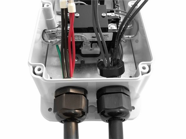
Insert Input cable through the cable gland on the Left and tighten.
-
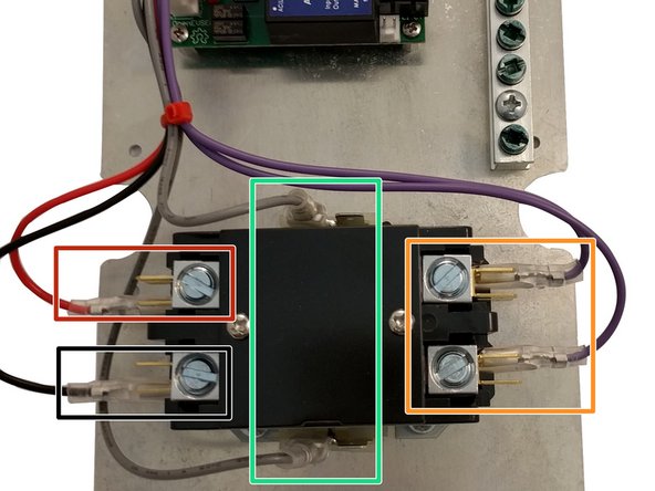
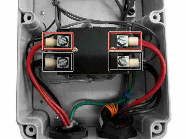
Connect AC Input 2 to the relay top left power terminal.
-
Connect AC Load 2 to the relay top right power terminal.
-
Connect AC Input 1 to the relay bottom left power terminal.
-
Connect AC Load 1 to the relay bottom right power terminal.
-
Sleeve Ferrules must be installed on cable ends. "Standard" cables purchased from OpenEVSE include pre-crimped ferrules. Digikey Part
-
-
-
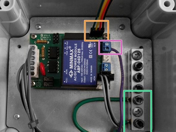
Connect the AC Input Earth Ground to the Ground block.
-
Connect the EV Output Earth Ground to the Ground block.
-
Connect the EV Output Control Pilot (CP) to PLT on the OpenEVSE Controller.
-
Connect Display cable (4 wires) to the OpenEVSE Controller.
-
-
-
Power ON. Use caution.
-
A OpenEVSE programmer can be used to power the controller to adjust contrast. Note there will be errors (this is normal) as not all systems are powered.
-
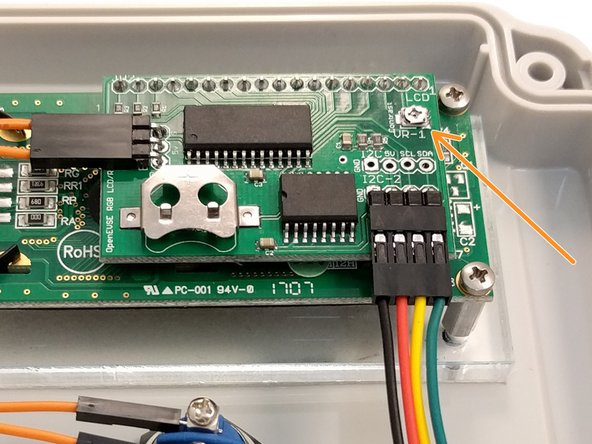
If needed - Adjust LED contrast (VR-1) Be very careful not to touch any components while powered.
-
When adjusting, be gentle. Do not force past the stop in either direction. If forced past the stop, the part will no longer function.
-
Secure the enclosure lid. Tighten the screws slowly alternating across and top, middle and bottom.
-
-
-
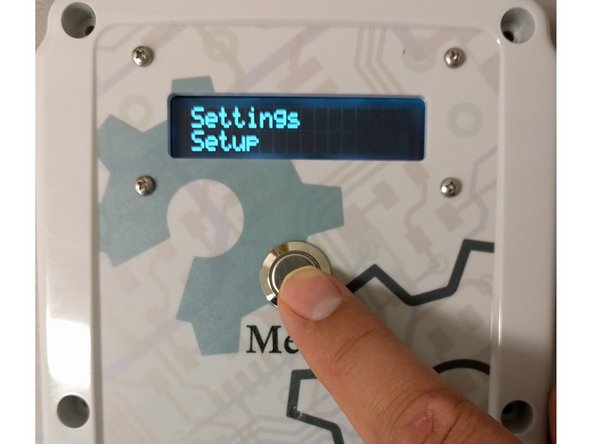
To Enter the Menu Press and hold the button (long press). Press and release (short press) to scroll through Options.
-
Set Current to desired Value (80% of your circuit breaker value). Menu => Setup => Max Current.
-
Enable GFCI Self Test. Menu => Setup => GFI Self Test
-
-
-
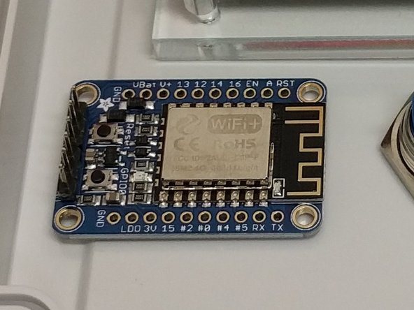
WiFi can be optionally added to Standard Kits. The WiFi Guide is here:
-
-
-
Current Measurement features can be added to Standard kits.
-
-
-


Cancel: I did not complete this guide.
2 other people completed this guide.
One Comment
Thanks for the tutorial.
Out of interest for other users, if using this charger on a Leaf, and after plugging the cable in - the car beeps three times, pauses, and then repeats, then it’s probably a dodgy microswitch tension in the J1772 handle!
I had to rip the handle to pieces, adjust the spring tension, and reassemble before the fault was fixed.
Cheers,
I.
Ian Patterson - Resolved on Release Reply