
Tools
No tools specified.
Parts
-
-
This guide provides the assembly procedure for SAE J1772 cable from parts available from at OpenEVSE.
-
-
-
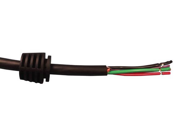
This guide uses 40A EVJT cable available from OpenEVSE.
-
Remove 3.25 inches of the outer jacket.
-
Strip and retain insulation from RED, BLACK and GREEN wire 1/2 inch (0.50").
-
Strip and retain insulation from Purple wire 3/8 inch (0.375")
-
Cut orange wire flush with outer jacket.
Is the purple wire in your description Control pilot or proximity detection? I am replacing a plug on an original Volt EVSE and the cable colors are ( I used a multimeter on the Voltec j1772 plug I am replacing) :
Red - L1 goes to pin 1 on Volt j1772 plug
Black - L2 - goes pin 2 on Volt j1772 plug
Green - GND - goes to pin 3 on Volt j1772 plug
Purple/Black - goes to Pin 5 - prox detect on Volt j1772 plug
Purple/Grey - not used?
Also, I have never see the term "strip and retain" when referring to leaving the cut insulation on the wire. Now that I have struggled with the bare ends of the wires, I know what that means now.
Thomas Karches - Resolved on Release Reply
-
-
-
Slide gland onto the cable. The notched end should face toward the stripped conductors.
-
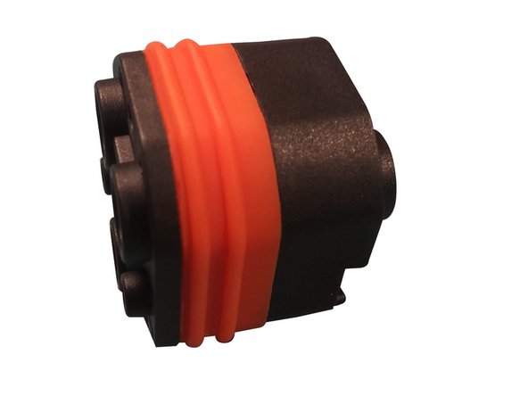
Assemble the pin guide/seal.
-
The plastic parts should make contact all the way around the orange rubber seal. If not check that the parts are in the correct orientation.
-
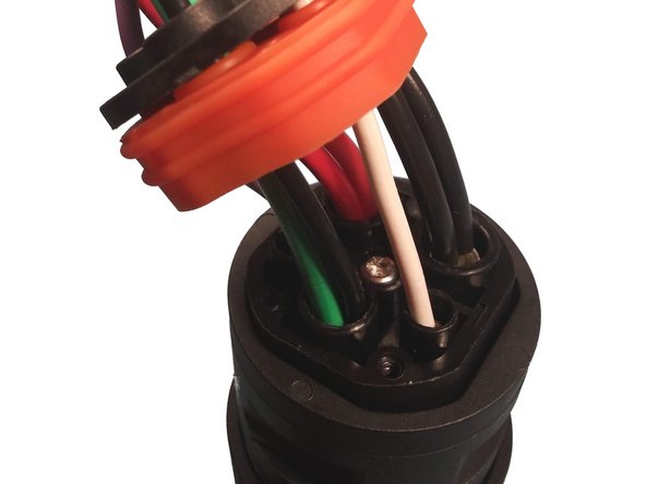
Insert conductors into the guide/seal, abbreviations are molded into the plastic part. PE = GREEN, CP = PURPLE, N - RED, L - BLACK
-
-
-
Cut 6" each of BLACK and WHITE 18AWG stranded wire.
-
Strip and retain 0.50" of insulation off both ends of the BLACK and WHITE wires.
-
Insert the 18AWG BLACK wire in the PE position in addition to the GREEN wire.
-
Insert a 18AWG WHITE wire in the hole labeled PP.
-
-
-
Remove insulation from the GREEN and BLACK wire.
-
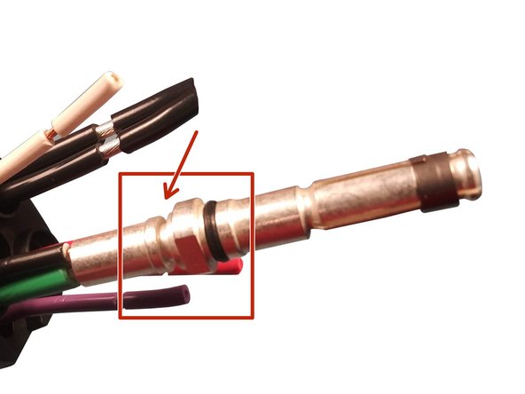
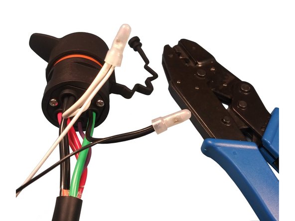
Insert the ground pin on the 10AWG GREEN wire and the 18AWG BLACK Proximity wire.
-
Note the Ground pin is different from the power pins. Note the notch near the area where the wire is inserted.
-
Crimp Ground pin with Pico Corporation 400B pneumatic crimping tool at 80PSI.
-
Recommended Die Pico 414DA-8N
-
Recommended locator - OpenEVSE J1772 Power/Ground
-
Soldering the pins is possible but requires a lot of heat to get solder to flow throughout. Crimping is recommended.
-
-
-
Remove the insulation on all the RED and BLACK power wires.
-
Insert the power pin on the BLACK wire(s) and crimp.
-
Insert the power pin in the RED wire(s) and crimp.
-
Note the power pins are different from the ground pin. Note the smooth surface along the crimp area where the wire is inserted.
-
Crimp Power pins with Pico Corporation 400B pneumatic crimping tool at 80PSI.
-
Recommended Die Pico 414DA-8N
-
Recommended locator - OpenEVSE J1772 Power/Ground
-
Soldering the pins is possible but requires a lot of heat to get solder to flow throughout. Crimping is recommended.
-
-
-
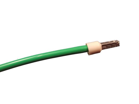
Insert the signal pin on the PURPLE wire and crimp.
-
Insert the signal pin on the WHITE wire and crimp.
-
Crimp Ground pin with Pico Corporation 400B pneumatic crimping tool at 80PSI.
-
Recommended Die Pico 414DA-12N
-
Recommended locator - OpenEVSE J1772 Signal
-
Soldering the pins is possible but requires a lot of heat to get solder to flow throughout. Crimping is recommended.
-
Slide up the pin guide onto the pins.
-
-
-
Insert pins into the connector housing.
-
Screw pin guide to the connector housing using 16 mm screw.
-
Slide orange seal and black plastic retainer down.
-
Screw retainer in with three 20 mm retainer screws.
-
-
-
Strip 0.50" off both the BLACK and WHITE wires from the push button switch assembly.
-
Remove the insulation off all BLACK and WHITE wires.
-
Twist WHITE wires together from bottom to top and crimp.
-
Twist BLACK wires together from bottom to top and crimp.
Remember to verify if the proximity resistors are there. 330Ohm parallel to switch and 150Ohm in series with the switch to ground. Search for proximity resistors j1772 if you need more info.
Elthon Lampe - Resolved on Release Reply
-
-
-
Position switch under the power and ground conductors as shown in the photo.
-
Fold WHITE and BLACK 18AWG wires in half.
-
Loosely tighten a tie wrap to keep the wires closely bunched.
-
-
-
Insert nose in bottom shell.
-
Insert cable gland in bottom shell, adjust position if necessary.
-
Insert switch in position in the bottom shell.
-
Secure cable in the strain relief.
-
Position tie wrap to avoid pinching wires in the shell seam during closeout.
-
Tension button spring and install button/spring/pin. Slid pin into the molded bushing.
-
-
-
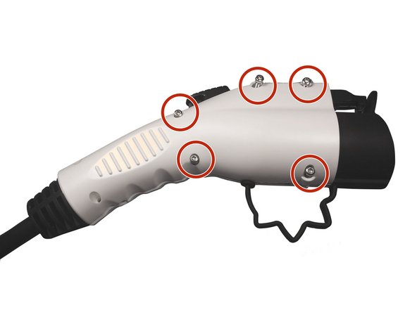
Insert dust cap end in shell halves.
-
Insert and tighten 16 mm screws in holes marked in RED.
-
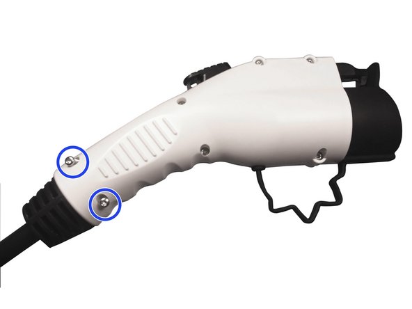
Insert and tighten 12 mm screws in positions marked in BLUE.
-
-
-
Remove insulation and crimp ring terminal on BLACK wires.
-
Remove insulation and crimp ring terminals on RED wires.
-
Remove insulation and Crimp Sleeve ferrule on GREEN wire.
-


Cancel: I did not complete this guide.
2 other people completed this guide.
8 Comments
For those looking for an affordable hydraulic crimper, I bought this one from Harbor Freight for $70 and it worked great:
Doug Silver - Resolved on Release Reply
The soldering went totally fine and my EVSE is back in service. I did initially install the black plastic retainer upside down, requiring a disassembly and re-solder (pay attention!). The second time went better anyway. If soldering, I would suggest using a piece of wood with a hole to hold the connector in place while soldering. Clamping in a vice may draw away too much heat. I used a Weller soldering gun which was capable of generating enough heat to properly create the solder joint.
Thomas Karches - Resolved on Release Reply
I'm looking for assistance replacing the 120v outlet plug that broke on my charger. It has green,. White, red, orange, and black wires. I'm assuming some Double up on both the the positive and negative terminals of the nema 6, 120v plug. If possible could you tell me which wires go on which terminals. Thank You
Will this work on Chargepoint Flex Home charger? I looked at the pinouts of this versus the one I currently have and Chargepoint has all 5 cables used.
Isku Zaboteur - Resolved on Release Reply
The 5th wire supplies power for a light on the Volt charger. Probably the same on the Chargepoint.
If you can’t get the Plug here - it is on Amazon B08XWD2XHX
Jack Gratteau - Resolved on Release Reply
I didn’t have the crimp tool - my Weller Soldering Iron was OK for the small terminals, but no way was that going to get the large terminals done.
But I do have a spot welder - and that was perfect to instantly heat the terminal - each #8 wire was pre-tinned using the Weller - which then made a tight fit in the terminal
When I clamp it with the spot welder across the barrel - more solder at the ready - toggle the welder and the barrel quickly hits temp - add fresh solder at the wire joint - spritz with water spray to cool.
O-Rings never got toasty - perfect fit.
Jack Gratteau - Resolved on Release Reply