
Difficulty
Moderate
Steps
13
Time Required
02:00:00 - 03:00:00

User-Contributed Guide
This guide is not managed by the site's staff.
Quiz
0
Introduction
- Warning Assembly of a Electric Vehicle charging station requires wiring Alternating Current (AC) components that will be exposed to voltages from 100 to 250v. If you do not have the experience and knowledge required to safely work with AC voltages please consult with an experienced electrician for assistance and inspection of your work.
- Note Regularly inspect your charging station. Pay special attention to excess heat, components, handles, and wiring will be warm but they should not be HOT...
- Always Disconnect your charging station from power before performing an inspection and/or maintenance
Tools
No tools specified.
-
-
Place 4 foam washers on 4 1/2" wide head screws.
-
Flip lid upside down and stack... Foam seal, then LCD clear window (remove Protective coating from both sides) and finally the LCD Window Brace (remove protective coating).
-
Place the 4 - 1/2" Screw through the lid with the foam washer on the outside. Compress foam and thread the 4- Hex Standoffs. Tighten each one hand tight compressing the foam.
-
-
-
Mount the water resistant button switch to the enclosure lid. Do not over tighten seal, if squeezes out of place the button is too tight.
-
Test enclosure lid again for water tightness. Spray water around the LCD window and button and ensure water does nor leak to the back side of the lid. Adjust as necessary.
-
Using 4 - 5/16" wide head screws. Mount LCD module to the lid.
-
Screws should be secure. Take care not to over tighten.
-
Connect the 3 pin cable to the LCD module. Strip wires about 1/2", fold in half stripped wire and screw into the switch screw lugs.
-
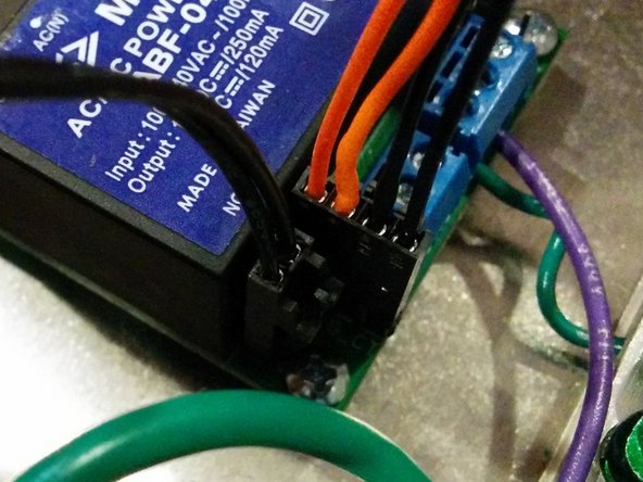
Connect 4 pin connector to LCD note the color that represents Ground (Green as pictured).
-
-
-
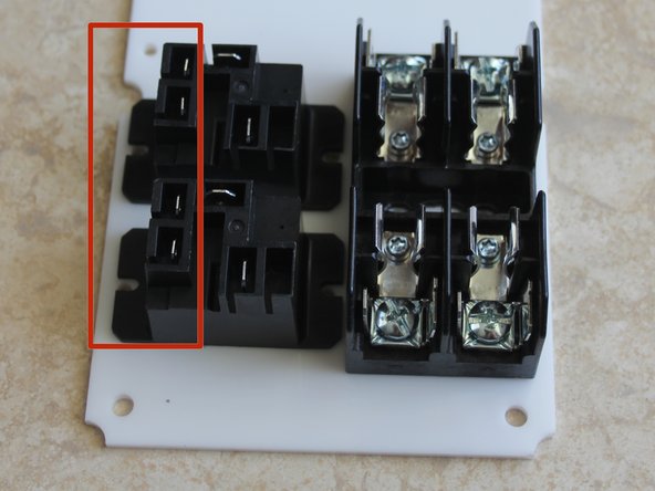
Your Charging station can be built with AC input Left and J1772 Right or opposite. Flip mounting plate to desired position. Fuses will line up with AC input and relays J1772 cable.
-
Mount fuse block with 2 - 3/8" screws from the top and lock nuts on the bottom.
-
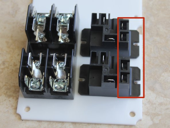
Position relays so the small tabs are to the outside for easier routing of low voltage wires.
-
Mount Relays with 2 - 3/8" screws from the top and lock nuts on the bottom.
-
-
-
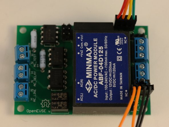
Mount OpenEVSE Plus board with 5/8" screws from the top.
-
Place nylon spacers between OpenEVSE board and mounting plate. Tighten Lock Nuts from the bottom. Do not over tighten.
-
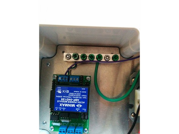
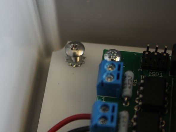
Mount Ground block with 2 - 3/4" screws from the bottom. Tighten Lock nuts from the top.
-
Connect OpenEVSE Ground to the ground Block. Ensure connections are secure.
-
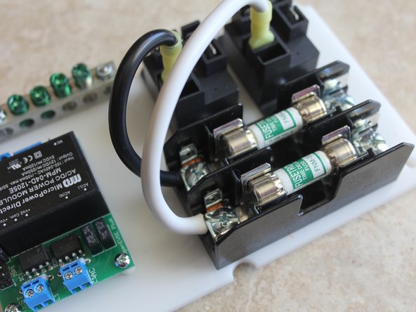
Crimp Yellow connector to 10AWG wire. Screw to the Fuse block. Wire can come from excess from AC cord or J1772 cable.
-
Ensure crimps are secure. Do not solder connectors designed for crimping. Do not connect and disconnect terminal. If loose, discolored, or damaged replace immediately.
-
-
-
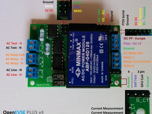
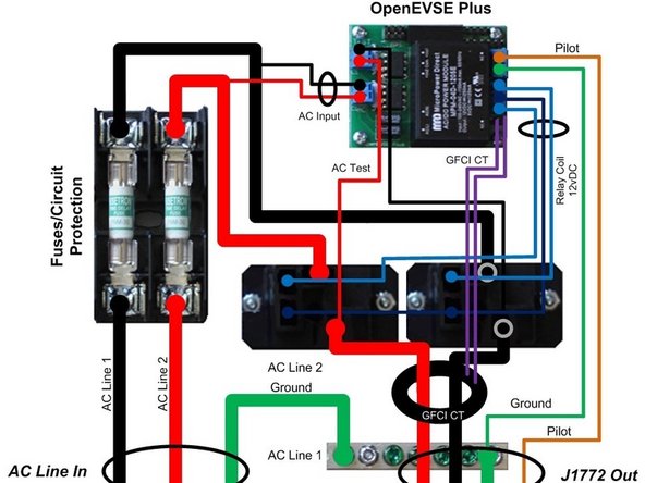
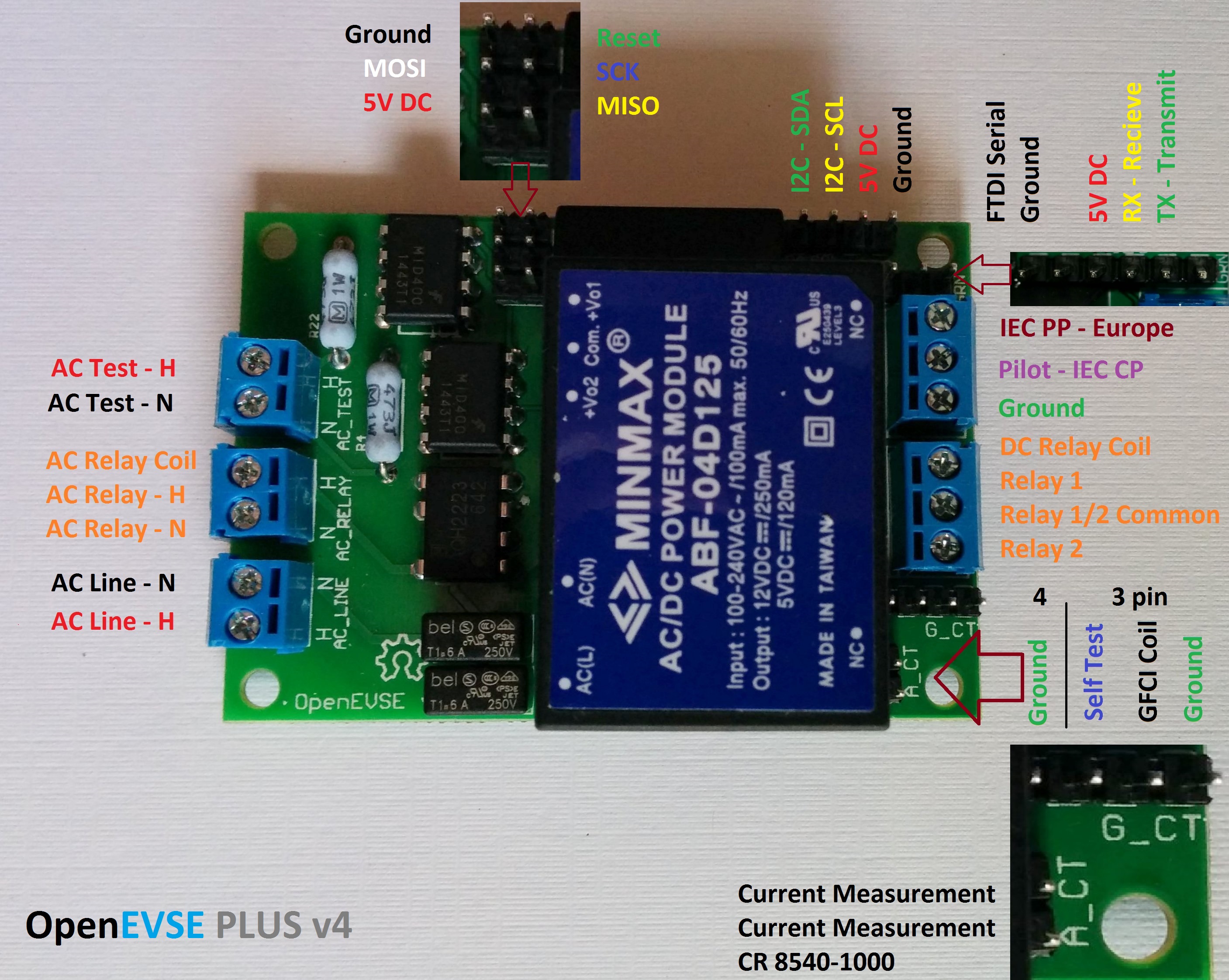
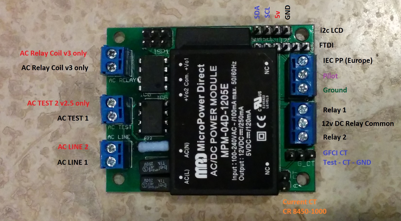
Review the connection diagram for the board you received in your kit. This guide depicts the latest board OpenEVSE v4.
-
v4 After July 2015
-
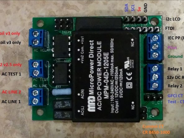
v2.5 Before July 2015
-
-
-
Connections are slightly different between board versions. Refer to these diagrams if the image in this guide does not match your board version.
-
-
-
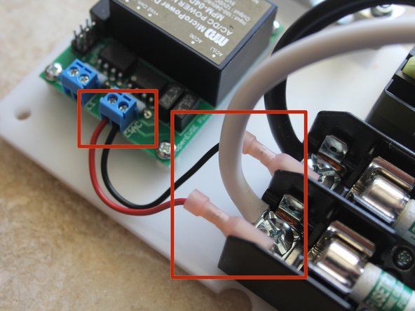
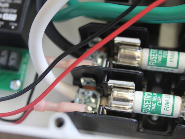
Crimp 22AWG wire to larger 1/4" pink QC connectors. Connect to Fuse block QC terminals.
-
Screw the 22AWG wires to the "AC Line - N" and "AC Line - H" block on the OpenEVSE board.
-
When connecting relay coil tabs. Ensure the QC terminal slides down the tab. It is possible to wedge the QC connector in by bending tab to the side.
-
Connect OpenEVSE common relay output (center pin) to 1 relay coil terminal on each relay using small pink QC connectors.
-
Connect OpenEVSE controller Relay 1 output to remaining pin on first Relay.
-
Connect OpenEVSE controller screw terminal Relay output 2 to remaining pin on second relay.
-
-
-
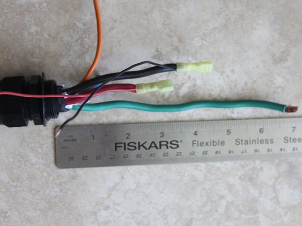
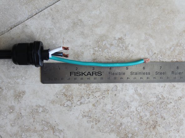
Prepare J1772 cable. Strip Cable back at least 8". Put Cable Gland on cable, it may take some effort depending on the diameter of the cable.
-
Ground and Pilot conductors should be 7" - 8" long.
-
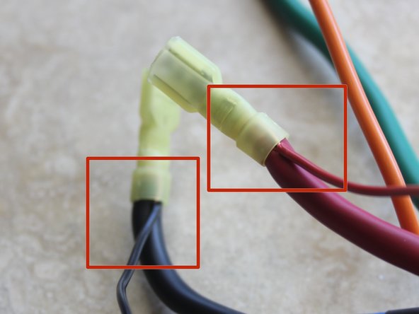
One Hot conductors should be about 5" long and the other slightly shorter. Crimp Yellow QC connectors to the Hot Conductors AND a 22AWG wire for the AC Test connections.
-
Ensure crimps are secure. Do not solder connectors designed for crimping. Do not connect and disconnect terminal. If loose, discolored, or damaged replace immediately.
-
-
-
Prepare AC cable (if Applicable). Strip back outer insulation 7". Put Cable Gland on cable.
-
Ground conductor should be 6" - 7" long.
-
Hot conductors should be 2" long.
-
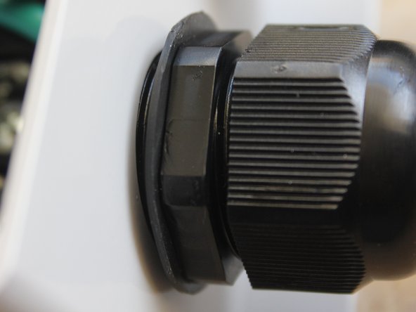
Secure AC Cord Cable Gland to enclosure on the side with the fuse block.
-
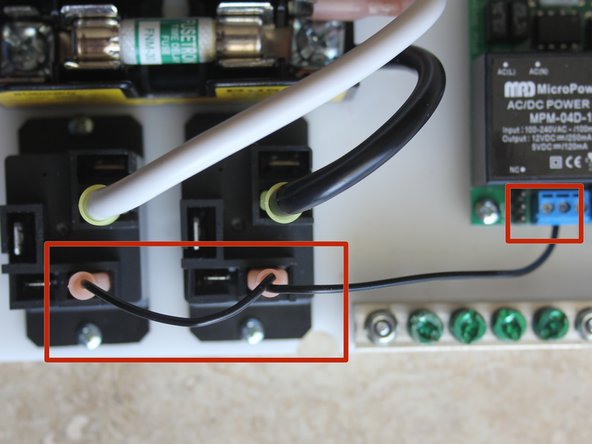
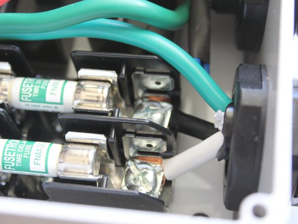
Connect Hot Wires to the fuse block.
-
-
-
Connect J1772 cable gland to the enclosure base.
-
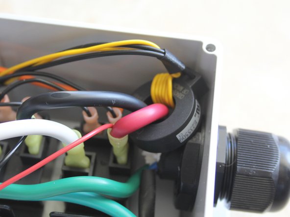
Run both HOT lines through the GFCI coil.
-
Connect J1772 Hot lines to relay outputs.
-
Connect the 22AWG wires from the QC connectors on the J1772 cable to the "AC Test - H" and "AC Test - N" to the OpenEVSE board.
-
Connect J1772 Ground to Ground block
-
Connect the Control Pilot from the J1772 cable to the OpenEVSE board.
-
Each manufacture uses different color codes for pilot. IT/Leviton - Orange, Yasaki - Blue, Quick Charge Power - Purple.
-
-
-
Connect 4 pin LCD cable to the OpenEVSE board.
-
Ensure the Ground from LCD connected to the ground on OpenEVSE board (ground is closest pin to board edge).
-
Colors of 4 pin connector varies and may not be the same as the image.
-
-
-
Connect the GFCI coil with self test loop to the 4 pin connector. Orange Self test wires to the inside Black GFCI CT wires to the outside.
-
Connect the current measurement CT to the 2 pin connector (either direction is fine).
-
-
-
To Enter the Menu Press and hold the button (long press). Press and release (short press) to scroll through Options.
-
Value kit - Set "Backlight Type" to Monochrome. Menu => Setup => Backlight Type.
-
Set Current to desired Value. Menu => Setup => Max Current.
-
Enable GFCI Self Test. Menu => Setup => GFI Self Test
-


Cancel: I did not complete this guide.
8 other people completed this guide.
7 Comments
Hello. I have just made time to build my 30A charging station I bought over 3 years ago. Upon boot up, the display reads "earth ground test failed". Is there any issue with using the charger with this failure? I have been unable to find the cause of this problem and am now assuming its a firmware issue. Thanks for the help.
Cheers,
Lee
Dear all,
Does anyone know which default firmware version should be downloaded onto the OpenEVSE v4 - Universal EVSE Controller when implementing the Discontinued - OpenEVSE 30A Charging Station on this page?
GitHub repos:
https://github.com/lincomatic/open_evse/...
https://github.com/OpenEVSE/Default_Firm...
Best,
Peman
Peman Montazemi - Resolved on Release Reply
I'm totally lost at this point - I bought the J1772 cable from this site to install and it has 7 wires - not the 5 listed in the guide. It has 2 red wires and 2 black wires - do I need to tie them together into one? Also, where goes the ground wires attach to this - do they just go into wherever there is space on the grounding bar?